| Chapter 1. Basic Machining and Tips Dimensional Tolerance  Necessity of Dimensional Tolerance
It is almost impossible (and sometimes uneconomical) to maintain the strict degree of accuracy as listed on a plan. To accommodate this, it is normal to display measurements with a plus or minus (+/-) tolerance which allows for some margin of error. Care needs to be taken however when determining such +/- tolerance, particularly where there are mating parts. For example, a shaft which is machined to its maximum tolerance may not fit a gear center that has been machined to it minimum tolerance or an unsatisfactory loose fit would result from the shaft being machined to its minimum tolerance with the gear center machined to its maximum tolerance. Usually, the dimensional tolerance is decided at the design stage and a Machinist must take care to apply the required dimensional tolerance and to ensure that discrepancies are not introduced as a result of poor workmanship of measuring techniques.  Dimensional Tolerance of a Shaft and a Hole
Figure 1 shows the plans of a fish robot's joint. In the plan, a shaft is inserted in the holes of Parts 1 and 2. The diameter of the holes are required to be on the plus-side of the dimensional deviation, and the diameter of the shaft is required minus-side of the dimensional deviation. Part 2 is inserted a slot of Part 1. Then the slot of Part 1 must have a plus-side dimensional deviation, and the size of Part 2 must have a minus-side dimensional deviation. Additionally, holes of many "commercially available" mechanical parts, such as gears and couplings, are already finished to plus-side dimensional deviations.
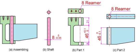 Fig. 1, Dimensional Tolerance of a Shaft and Holes
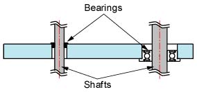
Installation of a Bearing
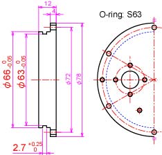
A Slot for an O-ring
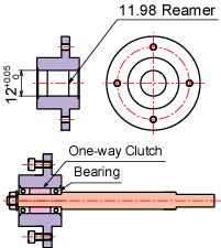
Installation of an One-way Clutch
Surface Finish
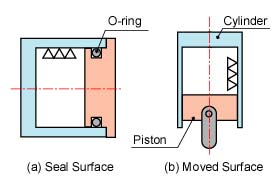
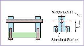
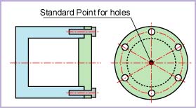
The Standard SurfaceAs described above, we cannot always finish the actual size to the same as that stated in a plan. In order to achieve the required degree of accuracy, we need to determine a "standard reference point" and plan the measurements from this point for an example of mating parts. In the case of mating parts (see Figure 6), these are where the parts mate is often used as the reference point as this provides a common reference point on both parts (see figure 7). Care needs to be taken when planning reference points as any errors can be accumulative resulting in parts not fitting together. The reference point varies from job to job as the complexity of shapes provide many challenges to accurate measuring and setting-out. Then it is important to decide the standard surface for measuring of the length or the machiningof the location. If the decided standard surface is not suitable, errors are piled up, and the completed parts often cannot be constructed as the completed machine. First, see the part plan carefully, and consider where is decided the standard surface. The deciding of the standard surface of a part is different by the shape or how-to-use. When several boards are constructed, the surface touched other parts is very often decided as the standard surface (see Figure 6). When the we make holes in a circumference, the center of circle is very often decided the standard point (see Figure 7).
| ||||||||||||
| Contact khirata@nmri.go.jp |