| Chapter 3. How to Use a Lathe
Using a Cut-off Tool
 Cutting-off Tool Cutting-off Tool
A cutting-off tool, which is often called a parting tool or grooving tool,
is one of the important cutting tools for the lathe processing.
Generally, the cutting-off tool touches to the material vertically, and
is moved to the vertical direction only. As a fundamental rule, it must
not be send the side direction, because its point is thin and weak.
Also, in the case of using the cutting-off tool, the rotating speed and
the sending speed must be lower, and the cutting depth must be small compared
with the general processing using the side tool. Please note that it is
needed much cutting oil in during the processing. |

Fig.1, Cutting-off Tool
|
 Setting of the Cutting-off Tool
The side faces of a cutting-pff tool is near parallel, thogh the edging
point is somwhat thick. When the tool set with a small leaning as shown
in Figure 2(b), the side face touchs to the material. If we notice a bad
shapeness or a bad sound, we must reset the leaning of the tool in careful.
When the cutting-off tool is set higher than the center of a material as
shown in Figure 2(c), the edge does not touch the material. The cutting-off
tool should be set to little lower than the center, as the same of a side
tool. Of course, a fundamental rule is that the height must be the same
of the center of the material. |
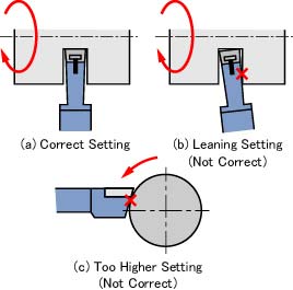
Fig.2, Setting of Cutting-off Tool
|
A Slot of O-ring
An O-ring is one of the seal dedvices, and used in many machines treating
gas or liquid fluid. Because it is very reasonable and standardized suitably.
The O-ring is installed into a slot as shown in Figure 3. When the O-rong
is installed around the outside surface as shown in Figure 3(a), the slot
can be make easily using the cutting-off tool. Figures 4 and 5 show the
examples of using O-rings. |
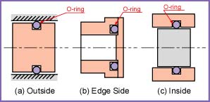
Fig.3, Installings of O-ring
|
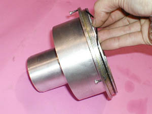
Fig.4, O-ring Slot of a Fish Robot
|

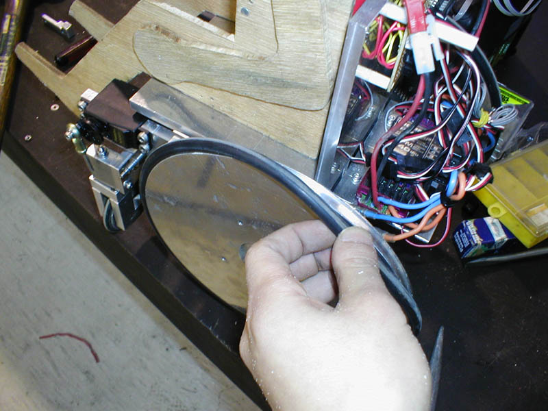
Fig.5, O-ring Tire of a Model Wheelchair
|
|
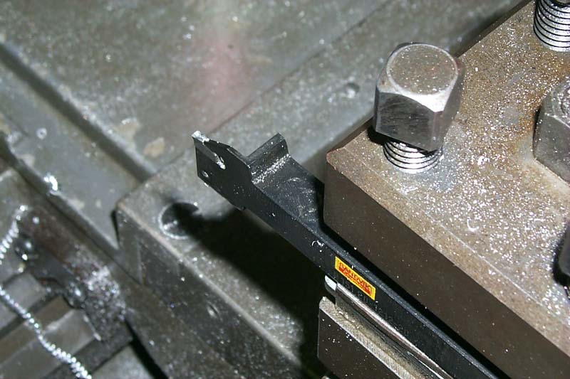
ADDITION: Making of an O-ring Slot at Edge Surface and Inner Surface When we make an O-ring slot at an edge surface as shown in Figure 3(b),
a special tool, of which look is similar the cutting-off tool, is used.
The edge of the tool is touched to the surface as shown in Figure 6, and
it is sent to the left slowly. The side face of the tool must not touch
the material, then it is too difficult to make a slot for a small O-ring.
Also the diameters of the slot are not accurate generally, then the way
of Figure 3(a) is better if possible. |

Fig.6, Slot for a O-ring installed Edge Surface
|
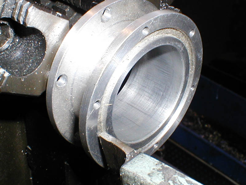
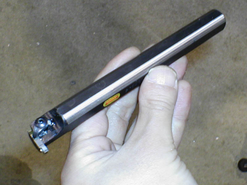
| When we make an O-ring slot at an inner durface as shown in Figure 3(c),
a special tool asn shown in Figure 7 is used. The processing of using the
tool becomes too hard. |
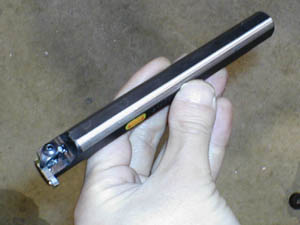
Fig.7, A Special Tool for an Inside Slot
|
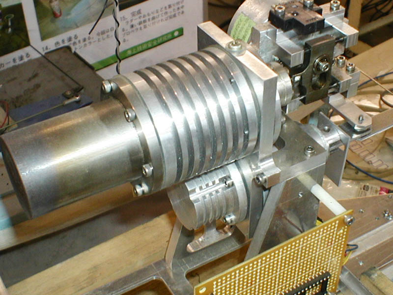
Fins of a Stirling Engine
Thermal engine, such as a Stirling engine, often has fins for cooling. Because the large area of heat transfer brings high performance.
The fins shown in Figure 8 can be created by the parting tool (prooving
tool). Please note that deep and thin fins need hard processings. |
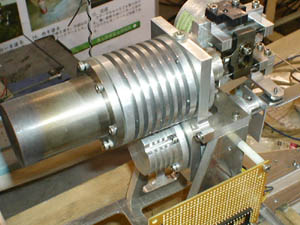
Fig.8, A Stirling Engine with Fins
|
[ Metal Working TOP ]
[ Hirata HOME ]
[ Power and Energy Engineering Division ]
[ NMRI HOME ]
|