| Chapter 4. How to Use a Milling Machine
Basic Operation of a Milling Machine
 How to Use a Milling Machine
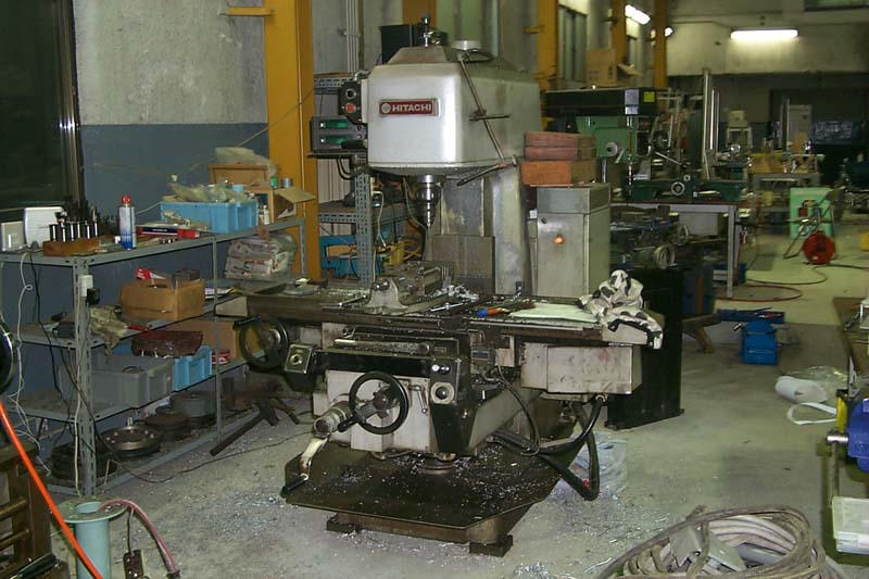
There are several types of milling machines. One is called a vertical milling machine as shown in Figure 1. It has high flexibility and good handling, though it has lower processing speed than another type of the milling machines.
In the milling macine, a rotating tool cuts a material. As the cutting
tool, a drill or an endmill is used. The table of the milling machine can
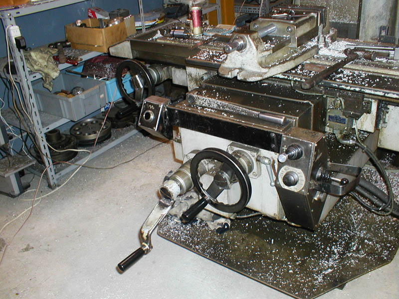
be adjusted accurately at the x- (side direction), y- (vertical direction)
and z- (height direction) axises with operating handles as shown in Figure
2.
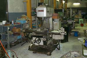
Fig.1, Milling Machine
|
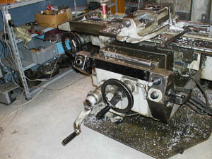
Fig.2, Handles of a Milling Machine
|
|
Accessories of Milling Machine
There are several accessories for the milling process except the cutting
tools. Following accessoriess are very useful.
 Vise
Vise
A vise is used for fixing of the material, and it is fixed to the table of the milling machine firmly. In the case of the cutting of a large-sized material, the vise can be remived from the table. But when the vise is installed again, it has to be fix accurately in the x-axis. We should not remove the vise except unavoidable cases. |
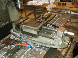
Fig.3, Vise
|
Digital Scale
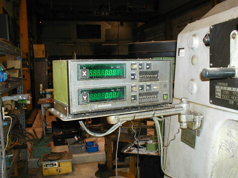
The table of the milling machine can be adjusted accurately at the x-,
y- and z- axises. We can adjust the positions with seeing the scales on
the operating handles. Moreover, if a digital scales as shown in Figure
4 is set, it is efficient that we operate with seeing the values of the
digital scale. The digital scale indicates with the minimum unit of 5/1000
mm of x- and y- axises. |

Fig.4, Digital Scale
|
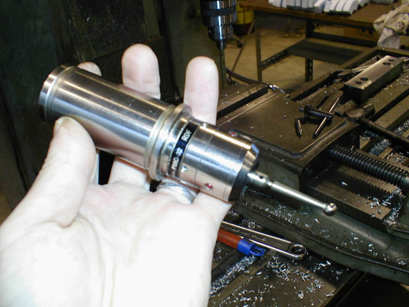
Point Master
In order to get a high accurate processing, the zero point must be adjusted exactly. A point master as shown in Figure 5 is the convenient tool for the adjustment. LEDs of the point master light when the point touches a metal material including the vise. We can find the zero point easily with this tool. |

Fig.5, Point Master
|
Mechanical Parts Made by a Milling Machine
The parts of various form can be made from using the milling machine. Mechanical parts made by the milling machine are introduced in followings.
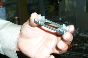
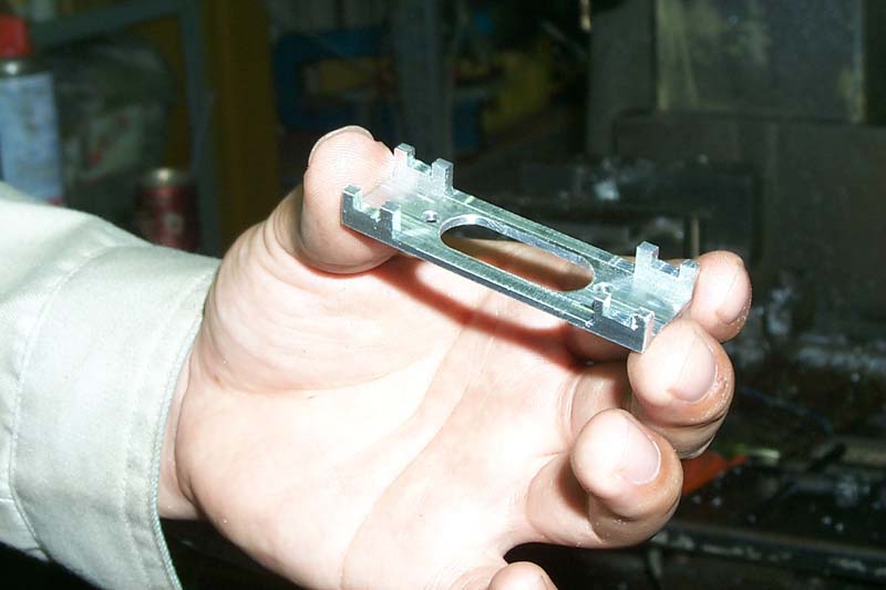
Fig.6, A Part of a Fish Robot
| This is the part used for the power unit of a fish robot, UPF-2001. Its
complicated form is made using an endmill. |
|
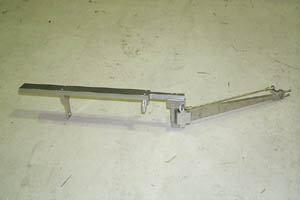
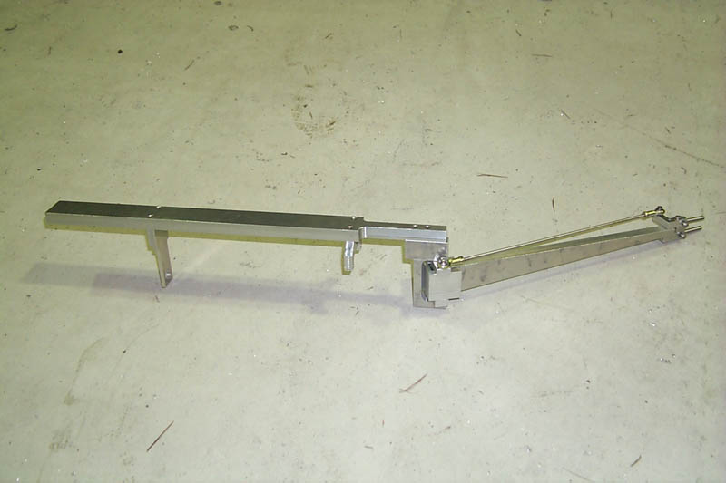
Fig.7, Backbone of a Fish Robot
| Some parts manufactured using the milling machine are put together. Almost
all parts are the simple form near a rectangular parallelepiped. |
|
(a) Connecting Rods
|
(b) A Drive Mechanism of a Stirling Engine
|
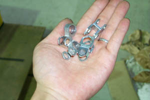
Fig.8, Connecting Rods of a Stirling Engine
| These are connecting rods of a 50 W Class Stirling engine, Mini-Ecoboy.
Since the thickness of parts is quite thin, the fixation to the table is
difficult, and it is hard to manufacture. And since it was the parts which
need remarkable accuracy, we had to be careful in the processing. |
[ Metal Working TOP ]
[ Hirata HOME ]
[ Power and Energy Engineering Division ]
[ NMRI HOME ]
|