|
|
Open-water test: [Data file]
[Performance Curve: eps | tif ]
|
In order to perform the self-propulsion computation, following three computations are required:
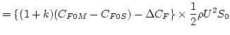
The self-propulsion computation is to be carried out at the ship point following the experimental procedure, i.e., the rate of propeller revolution ![]() is adjusted in such a way that the propeller thrust
is adjusted in such a way that the propeller thrust ![]() is balanced with the extrapolated full-scale resistance of the ship as follows:
is balanced with the extrapolated full-scale resistance of the ship as follows:
|
where
| ||
 |
||
|
| ||
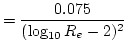
| (ITTC '57 frictional coefficient of the model scale,
|
||
| (ITTC '57 frictional coefficient of the full scale,
|
||
|
| ||
| Figure Number | Items | Remarks |
|---|---|---|
|
Integral variables: <towed> Form factor ( 1 + k ) at Fn = 0 Coefficients of total resistance (CT(Tow)), split into pressure (CP(Tow)) and friction (CF(Tow)) components at Fn = 0.26, Nominal wake coefficient ( 1 - w n ) <self-propelled> Coefficients of total resistance (CT(SP)), split into pressure (CP(SP)) and friction (CF(SP)) components, Propeller thrust coefficient ( KT ), Propeller torque coefficient ( KQ ), Thrust deduction coefficient ( 1 - t ), Effective wake coefficient determined from thrust identity method ( 1 - wT ), Propeller open water efficiency ( ηo ), Relative rotative efficiency ( ηR ), Advance ratio of propeller determined from thrust identity method ( J ), Propeller rate of revolution ( n [rps] ), Propulsive efficiency ( η ) |
Experimental results table |
|
| Fig. 2-1 | Axial velocity contours and cross flow vectors downstream of propeller
plane (x/Lpp=0.4911) |
download |
| Fig. 2-2 | Velocity downstream of propeller plane (x/Lpp=0.4911) at z/Lpp=-0.03 | To be compared with the experimental results download |
| Fig. 2-3 | Uncertainty analysis of the above item | UD = 5 % ( Proceedings of CFD Workship 2000 ) |
| Fig. 2-4 | Hull surface pressure contours ( port side view ) | download |
 |
 |
||
 |
||
 |
||
| (ITTC 1957 frictional coefficient line ) |
|
|
Roughness allowance |
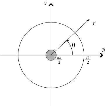
| Diameter of propeller | |
| Diameter of a propeller hub,
|
|
| Advance ratio
|
|
| By using the propeller thrust |
|
Thrust coefficient,
 |
|
Torque coefficient,
 |
|
| Torque coefficient in open water ( uniform flow ) | |
| By using the propeller thrust |
|
| Propeller rate of revolution [rps] | |
| Propeller torque | |
|
|
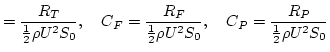
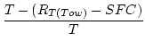
Total resistance in towed condition |
| Total resistance in self-propelled condition | |
| Skin friction correction | |
| Propeller thrust | |
Thrust deduction factor,
 |
|
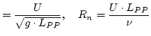
| Ship speed | |
| Propeller advance speed, determined by the thrust identity method,
|
|
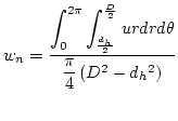
| nominal wake | |
 |
|
| where the origin is the center of propeller (see Figure) | |
Taylor wake fraction,
 |
|
Propulsive efficiency,
 |
|
Propeller open water efficiency,
 |
|
| Relative rotative efficiency,
|