|
| Figure Number | Items | Remarks |
|---|---|---|
|
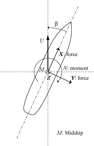
Integral variables: Coefficients of forces and moments, in x-direction: Total ( CX ) , split into pressure ( CXP ) and friction ( CXF ) components, and in y-direction: Total ( CY ) , split into pressure ( CYP ) and friction ( CYF ) components, Coefficient of yaw moment ( CN ) around the origin. |
||
| Fig. 3-1 |
Integral variables: Coefficients of forces and moments, CX, CY, CN, N / Y versus β |
To be compared with experimental results download |
| Fig. 3-2 | Uncertainty analysis of the above item | UD is not available. |
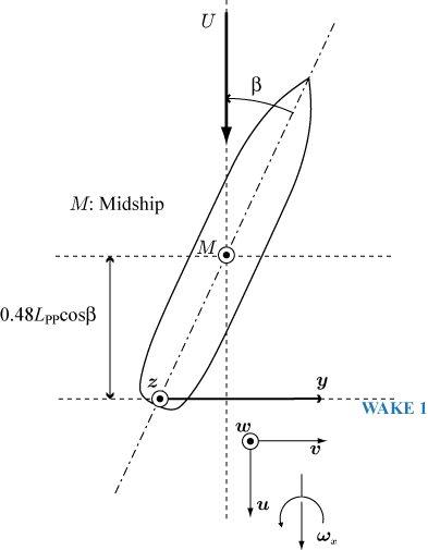
| Fig. 3-3 | Axial velocity contours and cross flow vectors on the WAKE 1 plane |
The WAKE 1 plane is shown in Figure 2. |
| Fig. 3-4 | Velocity on the WAKE 1 plane at z/Lpp=-0.05 | The WAKE 1 plane is shown in Figure 2. To be compared with experimental results download(β=0) download(β=6) download(β=12) |
| Fig. 3-5 | Uncertainty analysis of the above item | UD = 0.5, 1.0, 1.0 for u, v. w [%U] along the entire cut (proceedings of CFD Wordshop 2000) |
| Fig. 3-6 | Kinematic eddy viscosity ( νt ) and longitudinal component of vorticity ( ω x ) contours on the WAKE 1 plane | |
| Fig. 3-7 | Hull surface pressure contours( port, starboard and bottom side views ) | β = 6 and 12 [deg] |
| Fig. 3-8 | Hull surface pressure at x/Lpp = -0.4 and x/Lpp = 0.4 | To be compared with experimental results download |
| Fig. 3-9 | Uncertainty analysis of the above item ( USN, UV, E ) |
|
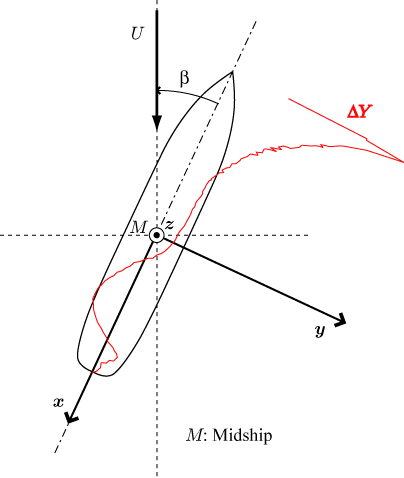
| Fig. 3-10 | Distribution of the side force component along the hull | To be compared with experimental results (02/Dec/2004 corrected) download ( β = 6 ) download ( β = 12 ) β = 6 and 12 [deg] |
| Fig. 3-11 | Uncertainty analysis of the above item |
UD = 14.1 [ % &Delta Yrange ] ( β = 6 ) UD = 8.66 [ % &Delta Yrange ] ( β = 12 ) β = 6 and 12 [deg] |
| Fig. 3-12 | Limiting streamlines ( Port, Starboard, and bottom views ) | β = 6 and 12 [deg] |
 |
 |
||
 |
||
 |
 |