|
Study on Design and Performance Prediction Methods for Miniaturized Stirling Engine
Design and manufacturing of a prototype engine

 Flowchart of the engine design
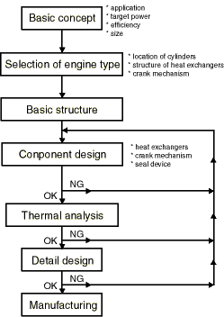 Design and manufacturing of a prototype engine are worked under a right flowchart. Like this flowchart, a basic concept for the engine design, a selection of engine type and a basic structure of a prototype engine are done in order. The prototype engine is manufactured after repeat of a conponent design and a thermal analysis.
In this page, the outline of these design process and characteristics of the prototype engine are described.
 Basic concept for the engine design
 The engine design has done to aim at miniaturized and light weight engine, simple structure and low product cost under the purpose of this research.
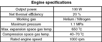
A right table shows target engine performance and an outline of engine configurations. The target output power is 100 W, and the target thermal efficiency is 20 %. These are decided in consideration of a working pressure, temperature and engine weight.
Helium or hydrogen have been used as the working gas of former high performance Stirling engines. But there are some problems that helium is expensive (in Japan), and hydrogen is dangerous to explode. On the other hand, it is considered that nitrogen is suitable as the working gas, because it is cheap and safety. Then the prototype engine uses both helium and nitrogen as the working gas. And it is considered to applicable them after the etstimations of the engine performance.
The maximum engine pressure, 1.1 MPa is smaller than the former high performance Stirling engine. It is caused by a portability of the engine.
The expansion space gas temperature, 650 deg C is also smaller than the former engine. In order to reduce the product cost, a general stainless steel ia used as a heater material of the prototype engine, though a expensive stainless steel is like Hasteloy X is used on the former engines.
 Basic structure of a prototype engine
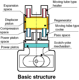 A right figure shows a engine structure, which was adopted after considerations about the engine type, a location of the piston and heat exchangers under above basic concept.
The regenerator is located in the displacer piston. The unique heat exchangers named a moving-tube-type are located above and below the disolacer piston. The heater and cooler consist on inner tubes and outer tubes. The innetr tubes move with the movement of the displacer piston.
The power piston and displacer piston are located in line like a beta-type Stirling engine. Then it has been able to realize the more compact and lighter weight engine than the former gamma-type Stirling engine.
Most important characteristics of the prototype engine are the moving-tube-type heat exchanger and the Scoth-yoke mechanism.
 Moving-tube-type heat exchanger
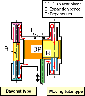 On a right figure, a left side shows a former byonet-type heat exchanger, and a right side shows the moving-tube-type heat exchanger. It is difficult to calculate the heat transfer performance of the moving-tube-type heat exchanger, because there are no experimental data of such type heat exchanger. So the heat transfer of the moving-tube-type exists on only circular spaces between the inner and outer tubes. Because the temperature of the inner tubes is droped by a heat conduction of the displacer piston. An experimental equations of a shell and tubes type heat exchanger is used the calculation.
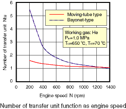 A left figure shows the calculated result of the relation between the engine speed and the number of heat transfer unit, NTU. In the case of the low engine speed, NTU of the byonet-type heat exchanger is lower than that of the moving-tube-type. But in the case of the high engine speed, their difference becomes very small.
Then in the case of the rated engine speed, 1000 rpm, the heat transfer performance of the moving-tube-type is considered to equal to that of the byonet-type.
 Scotch-yoke mechanism
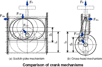 In order to consider the characteristic of the Scotch-yoke mechanism, it is compared the performance of the former cross-head mechanism. A right figure shows caluclulated models of their mechanisms. On their mechanisms, a crank pin force, Fcp, a main shaft force, Fcs and a guide beaing force, Fdm is lead from the piston force, Fp. Then, the mechanical efficiency of their mechanism is compared after the mechanical loss of each working part is calculated.
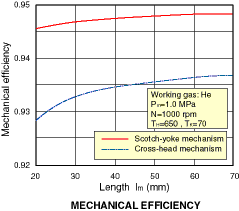 A right figure shows the calculated results of the relation the standard height length, lm and the equivalent mechanical loss at the piston stroke, 20 mm. The mechanical loss becomes higher, when the standard length becomes longer, because the guide beaing force decreases.
This figure shows that the mechanical efficiency of the Scotch-yoke mechanism is higher than that of the cross-head mechanism. Namely, the Scotch-yoke mechanism is more suitable for the compact engine than the former mechanism.
 Thermal analysis
As the thermal analysis, the engine performance is analyzed with considerations of a shuttle loss, a pumping loss, a heat conduction loss at the cylinder wall, a reheat loss and a pressure loss at the heat exchangers.
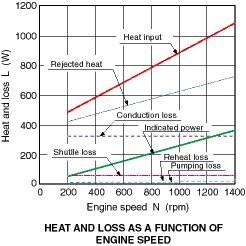 A left figure shows the analysis results of the relation between the engine speed and an effective heat input, a rejected heat, an indicated power and thermal losses. The indicated power is about 253 W at engine speed, 1000 rpm. It is reached the taget power enoughly. Also this figure shows the heat conduction loss and the shuttle loss is larger than other thermal losses. It is caused by the short length of the displacer piston, because the length of the displacer piston was decided shortly in order to decrease the pressure loss in the regenerator.
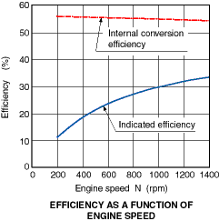 A left figure shows the analysis results of the relation between the engine speed, an internal conversion efficiency and an indicated efficiency. The internal conversion efficiency is about 55 %. When the engine speed is higher, the efficiency becomes lower slightly. It shows that the engine has a characteristic of small pressure loss.
On the other hand, the indicated efficiency becomes higher, when the engine speed is higher. Because the heat conduction loss and the shuttle loss which are not affected the change of the engine speed. Also the efiiciency is about 30 % at the engine speed, 1000 rpm.
 Construction of the prototype engine
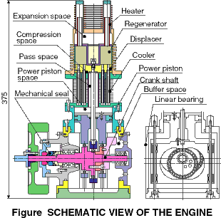 After repeats above considerations, A prototype engine shown is a right figure has been manufactured. The regenerator is located in the displacer piston. The moving-tube-type heater is located above the piston, and the same type cooler is located below the piston. The piston bore and stroke of the displacer and power piston are each 72 mm and 20 mm.
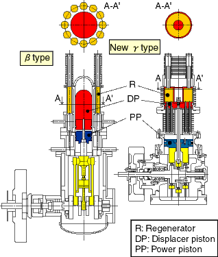 A left figure shows a comparison of the new gamma-type engine with a former beta-type engine. The new gamma-type becomes compact by the regenarator in the displacer piston, though the regenerator of the beta-type is located outside of the cylinder. As the result, every space in the new gamma-type engine is used effectively.
On the other hand, the beta-type engine is used the cross head mechanism. The Scotch-yoke mechanism used the new gamma-type engine is effective to miniaturize.
 Conclusion
(1) A prototype Stirling engine for a portable generator set is designed and manufactured.
(2) A compact and light weight engine is realized by adoption of the unique moving-tube-type heat exchanger and the regenerator in the displacer piston.
(3) The prototype engine is predicted to reach the target perfrmance under the results of the thermal analysis.
|
 Flowchart of the engine design
 Basic concept for the engine design
 Basic structure of a prototype engine
 Moving-tube-type heat exchanger
 Scotch-yoke mechanism
 Thermal analysis
 Construction of the prototype engine
 Conclusion
 Design and manufacturing of a prototype engine are worked under a right flowchart. Like this flowchart, a basic concept for the engine design, a selection of engine type and a basic structure of a prototype engine are done in order. The prototype engine is manufactured after repeat of a conponent design and a thermal analysis.
 The engine design has done to aim at miniaturized and light weight engine, simple structure and low product cost under the purpose of this research.
 A right figure shows a engine structure, which was adopted after considerations about the engine type, a location of the piston and heat exchangers under above basic concept.
 On a right figure, a left side shows a former byonet-type heat exchanger, and a right side shows the moving-tube-type heat exchanger. It is difficult to calculate the heat transfer performance of the moving-tube-type heat exchanger, because there are no experimental data of such type heat exchanger. So the heat transfer of the moving-tube-type exists on only circular spaces between the inner and outer tubes. Because the temperature of the inner tubes is droped by a heat conduction of the displacer piston. An experimental equations of a shell and tubes type heat exchanger is used the calculation.
 A left figure shows the calculated result of the relation between the engine speed and the number of heat transfer unit, NTU. In the case of the low engine speed, NTU of the byonet-type heat exchanger is lower than that of the moving-tube-type. But in the case of the high engine speed, their difference becomes very small.
 In order to consider the characteristic of the Scotch-yoke mechanism, it is compared the performance of the former cross-head mechanism. A right figure shows caluclulated models of their mechanisms. On their mechanisms, a crank pin force, Fcp, a main shaft force, Fcs and a guide beaing force, Fdm is lead from the piston force, Fp. Then, the mechanical efficiency of their mechanism is compared after the mechanical loss of each working part is calculated.
 A right figure shows the calculated results of the relation the standard height length, lm and the equivalent mechanical loss at the piston stroke, 20 mm. The mechanical loss becomes higher, when the standard length becomes longer, because the guide beaing force decreases.
 A left figure shows the analysis results of the relation between the engine speed and an effective heat input, a rejected heat, an indicated power and thermal losses. The indicated power is about 253 W at engine speed, 1000 rpm. It is reached the taget power enoughly. Also this figure shows the heat conduction loss and the shuttle loss is larger than other thermal losses. It is caused by the short length of the displacer piston, because the length of the displacer piston was decided shortly in order to decrease the pressure loss in the regenerator.
 A left figure shows the analysis results of the relation between the engine speed, an internal conversion efficiency and an indicated efficiency. The internal conversion efficiency is about 55 %. When the engine speed is higher, the efficiency becomes lower slightly. It shows that the engine has a characteristic of small pressure loss.
 After repeats above considerations, A prototype engine shown is a right figure has been manufactured. The regenerator is located in the displacer piston. The moving-tube-type heater is located above the piston, and the same type cooler is located below the piston. The piston bore and stroke of the displacer and power piston are each 72 mm and 20 mm.
 A left figure shows a comparison of the new gamma-type engine with a former beta-type engine. The new gamma-type becomes compact by the regenarator in the displacer piston, though the regenerator of the beta-type is located outside of the cylinder. As the result, every space in the new gamma-type engine is used effectively.