Research of Stirling Engines at National Maritime Research Institute

We have studied on the Stirling engines since 30 years ago. Main contents of the study is as follows.
(1) Effects of a friction and gas leakage at a piston ring,
(2) Effects of a pressure loss at heat exchangers,
(3) Dynamic simulation for the engine control,
(4) Underwater vehicle with the Stirling engine,
(5) Design method for a small Stirling engine,
(6) Development of unique heat exchangers.
|
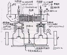
 The First Prototype Stirling Engine The First Prototype Stirling Engine
We started to study on the Stirling engine in 1970, when the Stirling engines had not been studied nearly in Japan. The right figure shows our prototype Stirling engine which was developed at that time. The crank case of the engine was diverted that of a general purpose internal combustion engine. The prototyoe engine was made experiments and has contributed to developments of belows experimental engines.
|
The First Prototype Stirling Engine
|
|
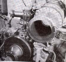
Inverted T Stirling Engine
A right photograph shows an experimental Stirling engine called 'Inverted T Stirling engine' in 1978. It consists of a hot cilinder, a cold cylinder which is located with 180 degrees of the phase angle, and a power cylinder (hot side) which is located with 90 degrees of the phase angle. This engine is pressurized in the crank case, and a mechanical seal is used as the external seal device. The maximum pressure in the working gas is set to 100 atm. The engine obtained the output power, 4 HP. It was a half of the design power. However, a lot of effective results were gotten as one of the genuine Stirling engines at that time.
|
Inverted T Stirling Engine
|
|
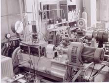
Piston Ring for Stirling Engine
At the same time of the development of the above experimental Stirling engine, we had started to study on seal devices such as piston rings for the Stirling engines. Several new type piston rings were suggested, and investigated their seal performance, friction performance and effects to the engine performance in detail.
A right photograph shows an components test bed for the piston ring and rod seal systems. The crank mechanism was diverted that of a Diesel engine. So the test bed could correspond to a large size of the seal devices.
|
Components Test Bed
|
|
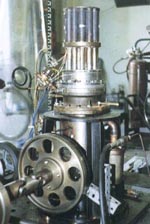
2 kW Class Experimental Stirling Engine
A more high performance Stirling engine was developed from 1985. A right photograph shows a 2 kW class experimental engine. The engine type is called a beta-type configuration, which is located a displacer piston and a power piston in the same cylinder. A heater and a cooler of the engine was adopted a small bayonet-type heat exchangers. This engine reached a target power, 2kW approximately. Also it contributed for a development of an engine control simulation described below.
|
2 kW Class Stirling Engine
|
|
Dynamic Performance Simulation
At the same time of the development of the above 2 kW class Stirling engine, we developed a dynamic performance simulation model for the engine control. This model simulates the engine performance with changing of the pressure and the temperature. Then it can analyze unstable behaviors of the Stirling engine.
Concretely, the pressure change is calculated by an adiabatic model. And the engine speed and output power is simulated by a solution of an equation for a rotating torque.
|
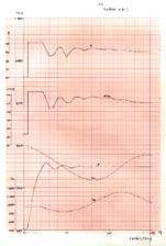
Result of the Simulation
|
|
Stirling Engine for Underwater Vehicle
Because the Stirling engine has a possibility of the high efficiency and can use a stability combustion, it is suitable for a power source of an underwater vehicle. Namely, it means that the high efficiency obtains a longer time operation than that of previous erectric battery and motor system. Also the stability combustion obtains an easy rejection of the exhaust gas into the sea.
We had started to study on the Stirling engine for the underwater vehicle since 1991, and suggested several power systems for the underwater vehicle. Also we studied on CGR combustion (Combustion Gas Recirculation) which utilizes a part of the exhaust gas.
|
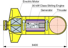
Underwater Vehicle for the Stilring Engine (Concept)
|
|
100 W Class Small Stirling Engine
A 100 W class small Stirling engine named 'Ecoboy-SCM81' has been developed since 1995. This engine was designed and developed under a project of a JSME committee, RC127, and made experiments at Ship Research Institute and Saitama University. This engine has reached a target power, 100 W using about 10 atm of a helium as the working gas.
A detail simuration model including a mechanical loss at mechanical devices and a thermal loss obtained in a crank case was developed under the experiments of the engine.
|
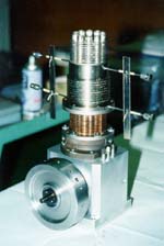
100 W Class Small Stirling Engine
|
|
A Small Engine and Apply to Fish Robot
The Stirling engine has good characterstics such as the high efficiency, low pollution and multi-fuel. However, the engine has several problems such as a heavy engine weight and a high production cost for the heat exchangers. In order to solve the problems, a 50 W class small Stirling engine 'Mini-Ecoboy' has developed since 1998. It is adopted several new technologies. The design concept is an adoption of a simple heat exchangers and an operation with a high engine speed. The target output power is 50 W at 4000 rpm.
We have disucussed an application for a fish robot (a fishlike swimming underwater robot) as one of the application of the Stirling engines since 1999. The discussed engine is a special type engine called a semi-free-piston-type, and it has a possibility of great decreasing of the mechanical loss.
|
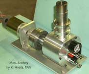
50 W class Stirling engine with Unique Heat Exchangers
|
|