Development of an Experimental Wheelchair
Introduction of the Hardware

 Introduction Introduction
 In this page, we show the experimental wheelchair for various experiments.
 Design Concept Design Concept
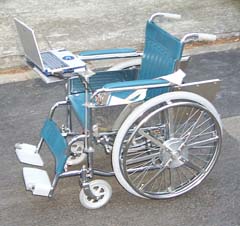
(1) The wheelchair carries a portable type personal computer to measure and calculate the technical data.
(2) The wheelchair should have easy handling of experiments. Thus, all of the erectric source use batteries without external erectric wire.
(3) In order to make easy and wide utilizations of the wheelchair at many educational or research institutions, it should have a low production cost.
Difficulties for the Measuring
(1) Because the distance between a hand lim and a wheel is too close, the size of a torque measuring mechanism is limited. Thus its location is difficult.
(2) Because the wheel has very stronger revolving fluctuation, it is important to discuss the accuracy of a wheel revolving angle measurement.
(3) Because the torque measuring mechanism rotates with rotating of the wheel, it is difficult to set the signal line.
Measuring System and Composition
 In order to understand the fundamental performance of a hand-operated wheelchair, it is needed to measure the drive torque and revolving angle of each wheel. The measured data is converted to the speed, locus, power and other technical results after calculating of the personal computer.
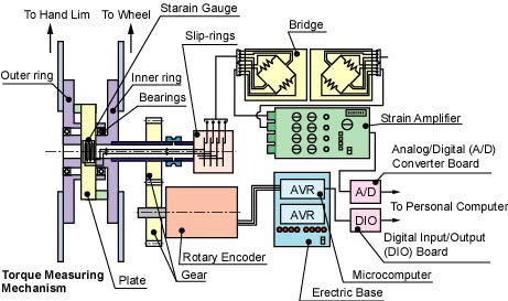
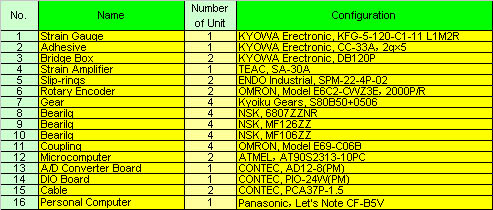
The figure at the right shows the measuring system. And the belows table lists main measuring components. A sampling frequency, accracy of the revolving angle (pulse numbers per one revolution of a rotary encoder) and the maximum torque were decided by the results of previous experiments before development of the experimental wheelchair.
Measuring of the Torque
 After many discussion, we decided to use general-purpose foil strain gages as a measuring method for the drive torque of a wheel. The torque converts a stretched or shrinked force of a plate. The strain gages meaure the strain of the plate. The strain gage is a low cost. It can also set to wide measuring range by changing the thickness or width of the plate.
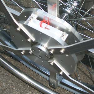
The photograph at the right shows the torque measuring mechanism. An inner ring is connected to a wheel. And an outer ring is connected to a hand lim. The inner and outer rings are supported by ball bearings. A plate, which is made of aluminum alloy (A2024S) and has 1.5 mm of thickness, is connected between the inner ring and the outer ring. The strain gages stick to both faces of the front side and the reverse side.
A shaft holding the wheel has a drill hole of 6.5 mm of diameter. A pipe, which is made of stainless steel and has 6 mm of outer diameter and 4 mm inner diameter, is set through the hole of the shaft with supporting by small ball bearings. The torque measuring mechanism rotates with rotating of the wheel, then the signal wires of the strain gages are connected to a unit of slip-rings at the edge of the pipe through in the pipe. They are then connected to an A/D converter board of a portable computer through a bridge circuit and a dynamic strain amplifier.
After the development of the torque measuring mechanism, we tried to confirm that the mechanism was suitable. As the result, the bearings supporting the inner ring and the outer ring had enough strength. When the hand lim was pushed with the side force (vertical force to the drive direction), the measuring mechanism was not affected. Also it was confirmed that the reproduce performance of the mechanism was enough after several calibrayions.
Calibration of the Strain gages
Measuring of the Revolving Angle
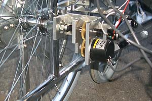 A hand-operated wheelchair has lower speed and stronger fluctuation than general rotating machines. Then in order to calculate the speed and locus from the measued revolving angle of the wheel, it is needed that the revolving angle be measure with high accuracy. Based on the such discussion, we decide to use a rotary encoder which generates 2000 pulses per one revolution for the measuring of the revolving angle. The rotary encoder is set a shaft through gears as shown in the photograph at the right.
The rotary encoder generates two phases of pulse with 90 degrees of phase. Two phases of pulse are converted to 12 bits (4096 counts) of signal by a microcomputer. It then input to a DIO (digital input/output) board of the portable type personal computer.
Program of a Microcomputer
Measuring Equipments and a Personal Computer
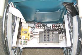
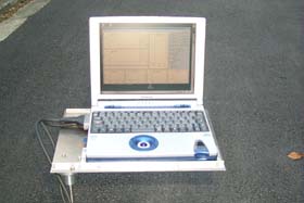
The bridge boxes, the strain amplifier and erecteric bases of the microcomputer are located on a aliminum plate at the back side of a seat. The portable type personal computer with the A/D converter board and DIO board is located at the front side or the back side of the seat. Both a driver of the wheelchair and another person can operate the computer. In the measurement, the screen of the computer indicates the detailed results such as the speed and locus.
|