Development of an Experimental Wheelchair
An Explanatory Note of the Software

 Introduction Introduction
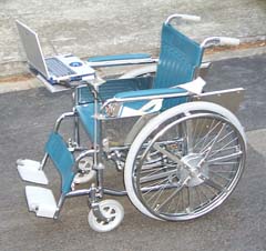 The measuring program named WchairMes**.exe, (** is version number) is used for the portable type personal computer of the experimental wheelchair. The program can also read and indicate the measured data.
 Functions and characteristics Functions and characteristics
(1) The program inputs the drive torque and the revolving angle of the wheels, and indicates the results.
(2) The program saves the measured data with two methods, 'Manual Save' and 'Auto Save'. They output comma type files.
(3) The program picks up the data of one stroke, and calculates a speed, a locus, a power and other technical results.
(4) the program reads and indicates the measured data.
Needed files
(1) Microsoft Visual Basic 6.0 SP4ÅiVB6ÅjRuntime Library: In the case of the PC which is not instaled VB6, it is needed to setup the VB6 Runtime Library.
(2) CONTEC AIO Library and DIO Library (for A/D converter DIO board): The libraries can be downloaded at CONTEC Home page. The libraries are needed even if the CONTEC hardware is not used, because the program uses several functions of the libraries.
(3) Initial file and Calibration file (WchairMes.ini and WchairMes.clb): The files is read at the same directory of the executive file, when the program starts.
Contents of the Program
This program consists of (1) Main screen, (2) Calibration screen, (3) Calculated result screen, (4) File option screen, (5) Data view screen, (6) Borads setting screen and (7) Text screen.
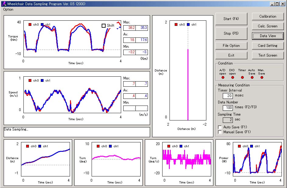
Main Screen
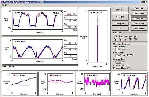
The Main screen is indicated when the program starts. The screen is used as follows.
 (1) Menu function
Other screens such as the Calibration screen or the Calculated result screen, are shown with the click of the command buttons at the right on the Main screen.
(2) Monitoring
It can be confirmed to work the hardwares and the measuring timer suitably by the indicators at the right on the Main screen. The 'A/D Open' and the 'DIO Open' are indicated green, when the A/D converter and the DIO board work suitably. The 'Timer' is indicated red, when the measuring timer does not work. And it is indicated green, when the timer is working. Also, the indicator is yellow, when the setting condition of the timer is not satisfied on the responce of a computer or a software. If so, you need to set to a longer sampling time, or exit other softwares of the Windows. The 'Auto Save' and the 'Man. Save' are indicated green, when the each condition is set as saving mode.
(3) Setting of the measuring condition
The measuring condition is set by the input at the right on the Main screen. When the sampling time (more than 1 ms with 1 ms step) or the data numbers (less than 2000) are changed, the measuring time (sampling time x data numbers) changes. These values can be changed even if the measurement.
(4) Start and stop the measurement
The program starts measuring when the 'Start' command is clicked. It stops measuring when the 'Stop' command is clicked.
(5) Data save
In the program, there are two methods of the data saving mode. One is 'Auto Save' and another is 'Manual Save'. They are set by checking the boxes at the right on the Main screen. When the 'Auto Save' mode, the program renames the file name, and saves the data after one measurement (sampling time x data numbers) automatically. When the 'Manual Save' mode, the program stops after one measurement, and you need input the file name. The file name is set at the File option screen.
(6) Indicating the graphs
The program draws graphs after one measurement, or with reading the data. These graphs are the relation between the operating time and the torque, the speed, the locus, the moving distance, the turning angle, the angular velocity of the turning, and the power. In the angles, positive value is the left direction, and negative value is the right direction.
(7) Function key
Several function keys work fundamental movements and setting. Thus in the measurement, the PC can be operated without a mouse. 'F1 Key' works to change data save modes. 'F2 Key' work to decrease the data numbers. 'F3 Key' work to increase the data numbers. 'F4 Key' works to start the measurement. And 'F5 Key' works to stop the measurement.
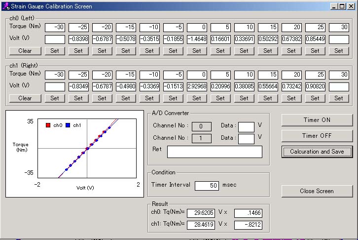
Calibration Screen
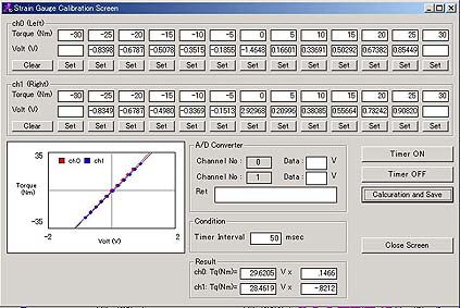 The Calibration screen is used for the calibration of the torque measuring mechanism. The screen also indicates the latest result of the calibration.
Flowchart of the calibration
(1) Click the 'Timer ON' command, and start to work the A/D converter. The measuring voltage is shown at the screen.
(2) Click the 'Clear' of each channel (ch0 is the left wheel, ch1 is the right wheel), and clear the voltage data.
(3) Set the calibration system (an arm of 300 mm length and weights of 3.4, 1.7 kg), and adjust the calibrated torque (-25 to 25 Nm).
(4) Click the 'Set' of each calibrated torque, and indicate the voltage at the text screen. Also the measuring point is plotted at the graph. (When the 'Set' is clicks again, the voltage is clear.)
(5) After input all data, click the 'Calculation and Save' command.
(6) An approximate equation is calculated, and draw a line at the graph.
(7) The calibration file named WchairMes.clb is saved in the same directory of the executive file. Also, another file named 'date + time' is saved in the same directory of the saving files.
(8) Click the 'Timer OFF' command after the calibration.
Calibration of the Strain gages
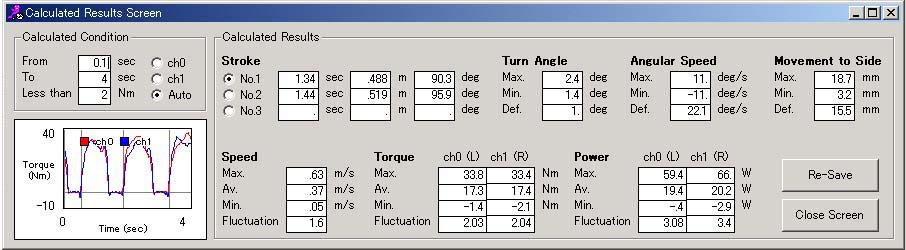
Calculated Result Screen
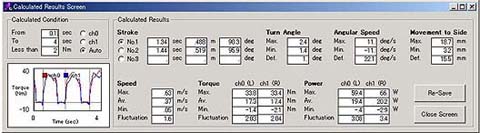 The Calculated result screen indicates the calculated results of one stroke.
Setting the calculated condition
The calculated condition, which are the staring time, the ending time and the distinction torque, is set at the right of the screen. The starting point is decided when the measured torque is over or under the distinction torque. As the condition of the distinction, you can sellect ch0, ch1 or Auto. In the case of the Auto mode, the starting point is distinguished from the torque that has the maximum torque in whole measuring torque. This program can calculate three continued strokes. If the data is re-culculated under other calculated condition, it is needed to read at the File view screen.
Drawing the graph
The grapg at the right of the screen shows the relation between the operating time and the torque. The vertical lines represent the starting points and the ending points. From the graph, you must judge if the calculated condition is sutable, or if the measuring data is sutable.
Indicating the data
The screen indicates many calculated results. From the left of upper screen, they are a cycle time per one stroke (sec), a distance per one stroke (m) and a revolving angle of the wheel per one stroke (degrees). Other text forms show the results of the sellected stroke, at the button at the left of the above results.
The maximum value, minimum value and the difference between the maximum and the minimum value of the turning angle (degrees), the angular velocity (degrees/sec) and the moving distance at the side direction, are indicated. Positive value is the left direction, and negative value is the right direction.
Also the maximum value, the average value, minimum value and the fluctuation ratio of the speed, the torque and the power, are indicated. The fluctuation is defined as (maximum-minimum)/average.
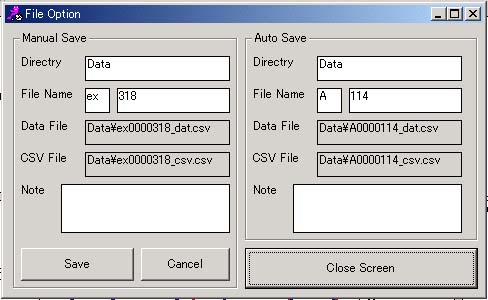
File Option Screen
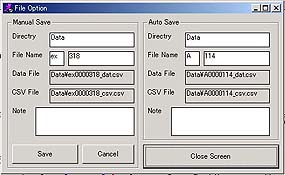 In the program, there are two methods of the data saving mode as described above. One is 'Auto Save' and another is 'Manual Save'. The File option screen sets the file names of the data saving.
Manual save
If the 'Manual Save' at the Main screen is checked, the File option screen is shown after one measurement. The file name and its directory are decided by the text forms at the left of the screen. The file name consists of an optional header, numbers and a decided enlargement (_dat.csv and _csv.csv). Two kinds of file are saved when the 'Save' is clicked. After the saving, the numbers of the file name plus one automatically.
Auto save
If the 'Auto Save' at the Main screen is checked, the files are saved as the file names of the text forms at the right of the screen. The File option screen is not shown at the 'Auto Save' mode. Also after the saving, the numbers of the file name plus one automatically.
Note
The text of the 'Note' is saved as one of the data of '***_dat.csv'.
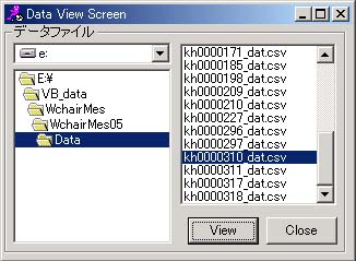
Data View Screen
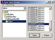 The Data view screen sellects a measured file for reading, reculculating and re-saving. After sellection of the file name, please click the 'View' command. The graphs and the calculated results are indicated at the Main screen and the Calculated result screen.
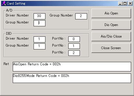
Boards Setting Screen
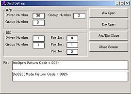 This screen is for the setting of the A/D conberter (CONTEC, AD12-8(PM)) and the DIO board (CONTEC, PIO-24W(PM)). You do not need to use and show the screen usually. When the return code (Ret.) is 000H, the boards works ready suitably.
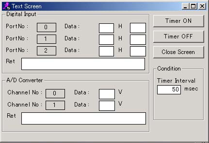
Text Screen
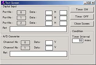 This screen shows the measuring values at text forms. You do not need to use and show the screen usually.
Data Format
The measuring program makes two types of the data file named '***_dat.csv' and '***_csv.csv'. They are a comma type format. The file of '***_dat.csv' consists of the measuring condition and the same results of the Calcilated result screen. The file of '***_csv.csv' consists of the measuring results such as the torque, the revolving angle and the power at whole operating time. These files can be read the general software like MS-Excel.
|