Prototype Fish Robot, UPF-2001
Hydrodynamic Performance of Stream-lined Body
Koichi Hirata and Syusuke Kawai, November 15, 2001

 Design Points for a Body of Fish Robot
A body shape of a fish robot affects strongly to propulsive performance like swimming speed. Of cource, the body is wished to have a few drag in the swimming. However, we can not to decide the body shape with only hydrodynamic considerations. Because, it must be well-balanced to the center of gravity and the buoyant position, and it is limited from the location of every mechanical components. The design points for the body are as follows.
(1) The body shape is matched to the location of mechanical components,
(2) Well-balanced design between the total volume (displacement) and the total weight is requered,
(3) Well-balanced shape between the center of gravity and the buoyant point is requered,
(4) A few drag force is requered,
(5) A few perturbation of water flow is requered around a tail fin,
(6) A simple shape is better for easy building.
|
Hydrodynamic Discussion
 Shape of Nose
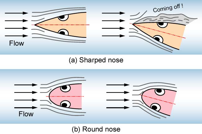
From hydrodynamic considerations, we discuss the difference between a sharped nose and a round nose(1). When the sharped nose inclines to the water flow, the water comes off easily from a body surface as shown in Fig. 1(a). It causes to have large drag force. On the other hand, when the round nose inclines to the water flow, the water is hard to come off. Then it maybe have a few drag.
The fish robot, which swims with oscillating a tail fin to the right and the left, moves its nose to the right and the left too. Therefore, the round nose is better to the nose shape in the groundplan (upper view).
|
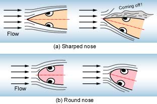
Fig. 1. Shape of nose
|
Stream-lined Form
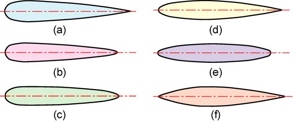
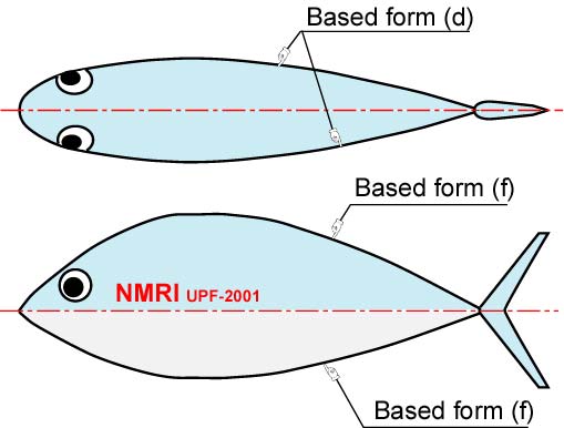
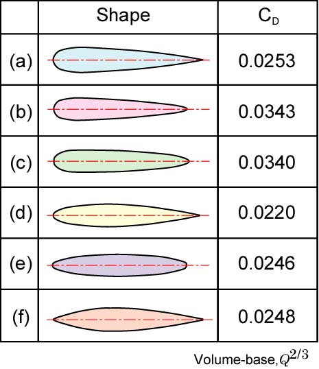
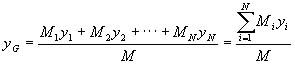
The stream-lined form gives smooth flow from the nose to the tail. It also has a few drag in the flow, so it is suitable for a shape of a fish robot. Figure 2 shows the well-known stream-lined bodys of revolution(1). In the bodys, Fig. 2 (d) has the most fewest drag. Therefore, we decide the shape of the UPF-2001 in the groundplan (upper view) based on the body line of Fig. 2 (d). the shape of the UPF-2001 in the sideplan is based on Fig. 2 (f) with the consideration of the location of components and the center of gravity. These body lines are adjusted as shown in Fig. 3.
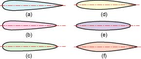
Fig. 2. Stream-lined bodys of revolution
|
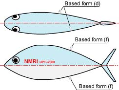
Fig. 3. Body Shape of the UPF-2001
|
|
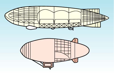
A high-speed airplane often use the wing or body with sharped edges like a lens. Such shapes are needed in supersonic speed moving. The speed of sound is about 1500 m/s in the water (about 340 m/s in the air). It is preposterously higher than the speed of a fish robot. Until you say, these shapes cannot be refered to a fish robot. We think that the shape of a fish robot can refer to the shape of an airship as shown in Fig. 4. It also is the same to the fish robot that the performance of the airship is affected by the relation between the buoyant force (volume) and the drag.
|

Fig. 4. Shape of airships
|
Estimation of Drag
In the case of a fish robot, it is very difficult to estimate the drag of the body. We try a simple estimation as follows.
(1) Reynolds number
A flow formation is affected by viscosity, velocity and a body size. In the case of the estimation for a fish robot, we need to calculate the Reynolds number, Re as defined the next equation at the first. And we should use experimental equations or coefficients in near the Reynolds number.

 (1) (1)
Here, L [m] is the delegated length. In the stream-lined form, the body length is uses as L generally. v [m2/s] is kinematic viscosity (the water; v=1.0Å~10-6m2/s), and u [m/s] is swimming speed. In the case of the UPF-2001, L is 0.8 m, u=1 - 3 m/s, then Re is lead to 8x10⁵Å`2.4x10⁶.
(2) Drag coefficient
Generally, drag force, FD [N] is shown in the next equation with the drag coefficient, CD, density, p (the water; p=1000 kg/m3), swimming speed, u [m/s] and the delegated area, S [m2].
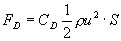 (2)
(2)
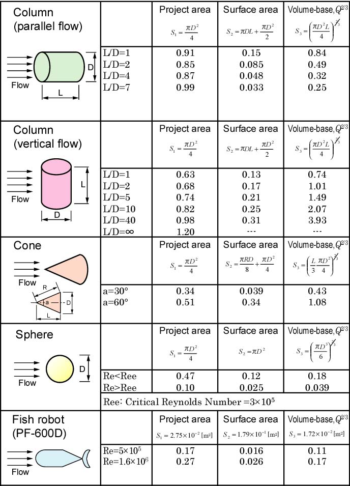
Here, the delegated area, S is decided regarding the shape or the application. For example, the maximum section area (the projected area) is used in an automobile. The area of a wing is used in an airplane. In the case of the stream-lined body of revolution, the projected area or surface area is used generally. However, we think that Q2/3, when Q [m3] is volume, is better for the delegated area, S. Because it is impotant to the relation between the volume and the shape in the fish robot.
The value of the drag coefficient, CD differs from the selection of the delegated area, S. Figure 5 shows converted drag coefficients with several delegated areas(1)-(4).
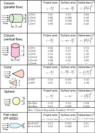
Fig. 5. Drag coefficients
(3) Drag coefficient of Stream-lined Form
Figure 6 shows the drag coefficient, CD of the stream-lined body of revolution in Fig. 2 using Q2/3 as the delegated area. From the figure, CD is in about 0.02 - 0.04. These value is very smaller than that of Fig. 5. Also, it is well-known that the ratio between the length, L and the diameter, D (L/D) affects to the drag coefficient, CD(1). And L/D=4.5 gives the most small drag coefficient.
From these discussion, we must decide the ideal body shape for the fish robot. However, it is difficult to adopt the ideal stream-lined body. Because the fish robot has the limits of the size and the location of components as described above.
|
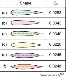
Fig. 6. Drag coefficient of stream-lined body
|
(4) Drag of the UPF-2001
Based on the above discussion, we calculate the drag force, FD [N] of the UPF-2001. As described belows, the total volume of the body, Q is 20420 cm3, and S is Q2/3=0.0747 m2. Figure 7 shows the relation between the swimming speed, u [m/s] and the drag force, FD with the parameter of the drag coefficient, CD. As an example, when CD=0.03 and u=3 m/s, FD becomes about 10 N (100 gf). This means that 10 N (100 gf) of propulsive force by a tail fin is needed for the swimming speed, 3 m/s.
|
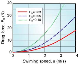
Fig. 7. Drag of the UPF-2001
|
Estimation of Displacement and Balance
Weight of Units and the Center of Gravity
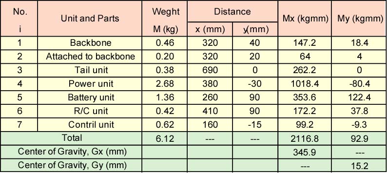
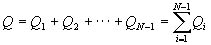
We measured the weights of components, and estimated the center of gravity. The total weight, M and the overall center of gravity of the fish robot, G (xGÅCyG) are calculated by the next equations with the number of each component, i=1ÅC2, ---, N, the weight of each component, Mi and coordinates from the standard point, xi and yi.
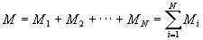 (3)
(3)
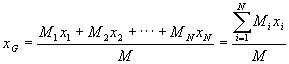 (4)
(4)
 (5)
(5)
Estimation of the Center of Float Position
When the buoyant point is not the same of the overall center of gravity, a fish robot can not keep a horizontal posture. In the case of the real development of the fish robot, it is not always clarified a machining accuracy of the body and the density of body materials, such as wood, adhesive and FRP. So, it is very difficult to predict the buoyant point accurately before building the body. We then thought simply the buoyant point as the following.
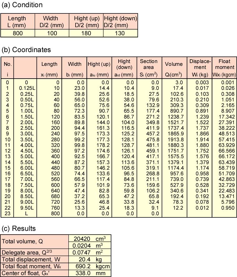
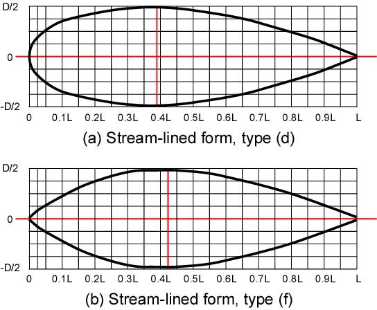
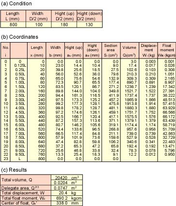
(1) We traced the stream-lined lines from a reference, and read their coordinates as shown in Fig. 8 and Table 1.
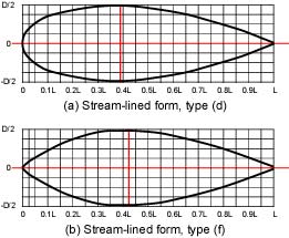
Fig. 8. Plans of the stream-lined form
|
Table 1. Coordinates of the stream-lined forms
|
|
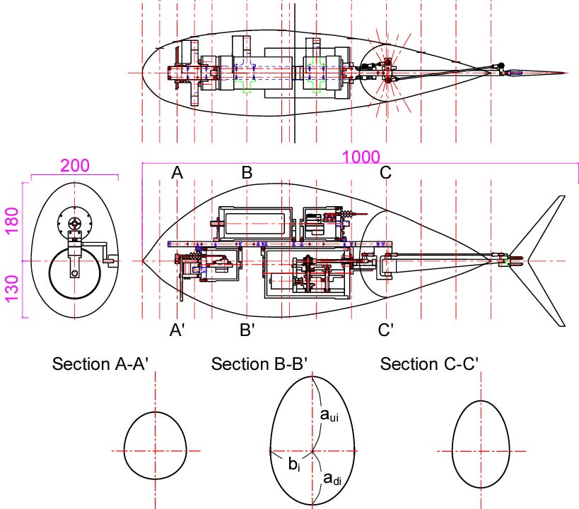
(2) The ratio between the body length and the diameter, L/D is adjusted to suit with the components. In the case of the UPF-2001, the body length, L=800 mm, the equivalent diameter in the groundplan (=width) , Db=200 mm, the diameter in the sideplan, Dau=360 mm (upper side) and Dad=260 mm (belows side) as shown in Fig. 9. Also in the discussion of the body, we built three body models as shown in Fig. 10.
(3) The body is divided to N, and each section is decided a variant ellipse with the upper radius, aui, the belows radius, adi and the side radius, bi as shown in Fig. 9.
|
Fig. 9. Cross section of the UPF-2001
|
|
(4) The area of an ellipse with radius of a, b is abpi. Then each section area of the fish robot, Si is calculated by the next equation.
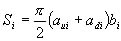
 (6) (6)
|
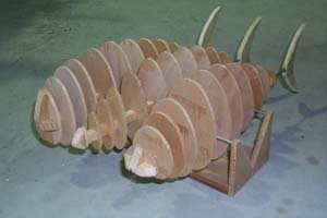
Fig. 10. Models of the body
|
|
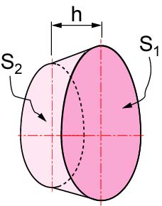
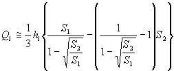
(5) The volume of a cone and a pyramid, Q is Sh/3 with the base area, S and the hight, h. Also, as an assumption, neighboring sections, i and i+1 have similar shapes. The volume between the neighboring sections, Qi [m3] and the displacement, Wi [kgf] are calculated by the next equations (see Fig. 11).
 (7)
(7)
 (8)
(8)
Here, S1 is a bigger section area, S2 is a smaller section area, and hi is the distance between the neighboring sections, p is specific gravity (density; p=1000 kgf/m3).
|
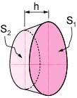
Fig. 11. Calculation of volume
|
(6) From the next equations, the total volume, Q [m3] and total displacement, W [kgf] are calculated.
 (9)
(9)
 (10)
(10)
(7) From the next equation, the buoyant point, G'(xG'ÅCyG') is calculated with the delegated distance between the standard point and each volume, Qi (the central point of sections), xi'.
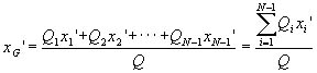 (11)
(11)
Estimated Results of the UPF-2001
|
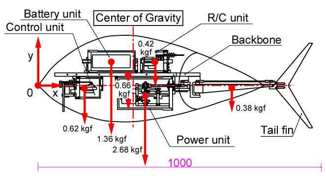
Table 2 and Fig. 12 show the measured and calculated results of the weights and the center of gravity. Table 3 shows the calculated results of the buoyant position and the displacement. The total displacement, 20.4 kgf is very bigger than the total weight, 6.1 kgf. However we think that it is a suitable value. Because, the weight of the body material is not included, and the body is not waterproofed.
Also, the center of gravity on the x-axis, xG=346 mm, is similar to the buoyant position, xG'=338 mm. The small difference can be adjusted by attaching a balancer.
If we need to consider the detailed balance, it is needed to compare the values of yG' and yG. But in the case of the UPF-2001, it is clarified that yG' is higher than yG. So, we do not calculated them.
|
Table 2. Weights of the units
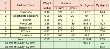
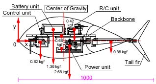
Fig. 12. The center of gravity of the UPF-2001
|
Table 3. The Center of Float position and Displacement
Conclusion
In this page, we discussed the body of the fish robot in the view of hydrodynamics, and described the arrangement to decide the body shape. Though they may be very nonsense, we wonder if the detailed hydrodynamic analysis realizes a high-performance fish robot. We believe that the above estimation is suitable for the development of our fish robot, UPF-2001.
References
(1) Mitsuo Makino, Hydrodynamic Drag and Stream-lined Form, Sangyo-tosyo, 1991, (in Japanese).
(2) Sachio Tomita, Hydraulics, p.157, Jikkyo-syuppan, 1993, (in Japanese).
(3) Japan Society Mechanical Engineerings, Mechanical Engineering, A5, p.97-106, Maruzen, 1987, (in Japanese).
(4) T. Takimoto, K. Hirata and M. Makino, Measurement of Drag of a Fish Robot and Hydrodymanic Discussion, Proc. of JSDE Tohoku branch, p.84-87, 2000, (in Japanese)ÅD
[UPF-2001]
[Experimental Fish Robots]
[ Fish Robot Home Page ]
[ Power and Energy Engineering Division ]
[ Hirata HOME ]
[ NMRI HOME ]
|