Prototype Fish Robot, UPF-2001
Detail Information of Power Unit
Koichi Hirata and Syusuke Kawai, November 26, 2001

 Structure and Characteristics
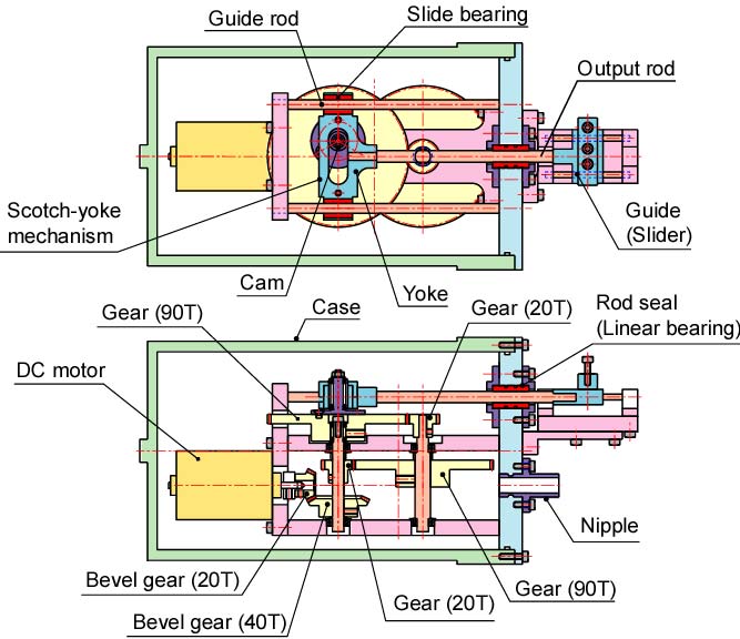
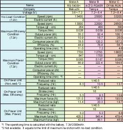
The power unit of the fish robot, UPF-2001 consists of (i) a D/C motor as a power source, (ii) a gear mechanism for reducing the revolution of the motor, (iii) a Scotch-yoke mechanism to change from rotating motion to reciprocating motion, (iv) seal devices for waterproof, and (v) a connecting mechanism to a tail fin. Table 1 lists the specifications of the power unit.
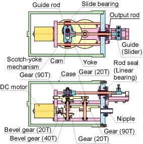
Fig. 1. Power unit
Click figure, and show a bigger one.
|
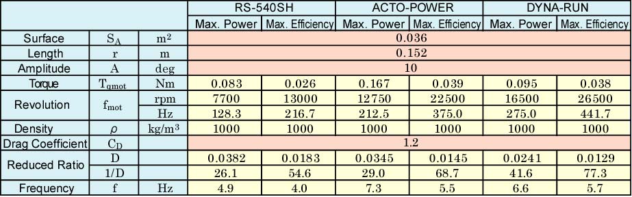
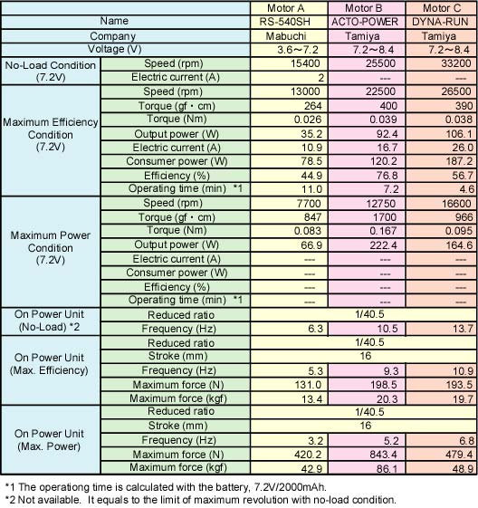
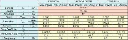
Table 1. Specifications of the power unit
Click figure, and show a bigger one.
|
 Compact and High-power D/C Motor
A D/C motor for a radio control model (R/C) is used as a power source of the UPF-2001. The D/C motor has smaller size, higher-power and better handling than a R/C servomotor and a pulse motor. Also, many types of the D/C motors are sold as a mechanical part, so it is not problem in power level or operating speed. However, it needs a reduced mechanism and a changing mechanism to reciprocationg motion. We prepared three types of the motor for the UPF-2001 as shown in Tables 1 and 2.
|
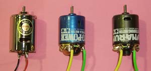
Fig. 2. D/C motors for a R/C model
|
|
Gear Mechanism
The compact and high-power D/C motor runs high speed, more 10000 rpm (167 Hz). So, it cannot move a tail fin with the same speed. A gear mechanism, which consists of six gears, is used for the UPF-2001 as the reduced mechanism. It reduces the speed of the motor to 1/40.5.
|
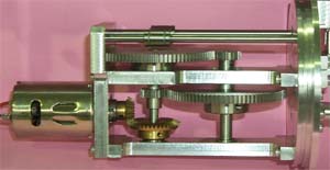
Fig. 3. Gear mechanism
|
|
Scotch-yoke Mechanism
A Scotch-yoke mechanism is adopted as the changing mechanism from rotating motion to reciprocationg motion. The Scotch-yoke mechanism has a crank disk with a shifted shaft. the crank disk reciprocates the yoke which has a oval hole. The stroke of the reciprocating motion can be adjusted by a crank radius. In the case of the UPF-2001, the stroke is set to 16 mm. The yoke has linear ball bearings, so the mechanism has ideal motion without the strong force to a seal device.
|
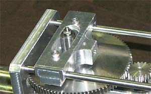
Fig. 4. Scotch-yoke mechanism
|
|
Seal Mechanism for Waterproof
A linear bearing (ASK Co. Ltd.) is used as the seal device of the reciprocating motion. Because its surface is PTFE (Teflon), it is needed to decrease the side thrust force of an output rod. The Scotch-yoke mechanism and a connecting mechanism, which is described belows, are very effective for decreasing the side thrust force. Also, the case, which covers the motor and the mechanisms, is waterproofed by a rubber "O" ring.
|
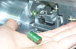
Fig. 5. Seal mechanism
|
|
Connecting Mechanism to the Tail
The figure to the right shows the connecting mechanism from the output rod to the tail fin. In order to keep seal performance of the linear bearing, the connecting mechanism has simple guides .
|
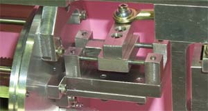
Fig. 6. Connecting mechanism to the tail
|
|
Outline of the Mechanical Design
To transmit the power from the motor to the tail fin, we need to decide suitablythe size of a fish robot, the power of the motor and the reduced ratio of the gear mechanism. In this chapter, we introduce a simple calculation method for the mechanical design.
The Maximum Torque
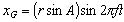
The tail of a fish robot is replaced to a flat plate as shown in Fig. 7. In the figure, G is the center of gravity, r(m) is the length between G and a joint, and A(deg) is an amplitude of the tail fin. When the tail fin moves with sine-curves, stroke of G, xG(m) is calculated approximately by the next equation.
|
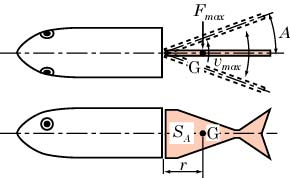
Fig. 7. A simple model for calculation
|
 (1) (1)
Here, f(Hz) is frequency of the tail fin, and t(s) is time. Therefore, the velosity og G, vG(m/s) is calculated by the next equation.
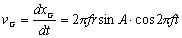 (2)
(2)
When cos(2pift)=1 (when the tail fin moves on the center line), the velosity has the maximum value, vGmax.
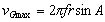 (3)
(3)
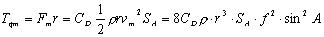
The maximum force, FGmax is calculated by the next equation with the surface of the flat plate, SA.
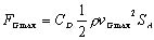 (4)
(4)
Here, CD is drag coefficient (CD=1.2), p is density of water (p=1000 kg/m3. Then, the maximum torque, Tqmax(Nm) is caluculated by the next equation.

 (5) (5)
From these equations, the maximum torque, which is needed to move the tail fin, is calculated.
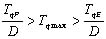
On the other hand, the torque of a final shaft of the motor becomes Tqmot/D(Nm), using the torque of the motor, Tqmot(Nm) and the reduced ratio, D. When Tqmot/D is bigger than Tqmax, the motor can drive the tail fin.
Mean Power
In order to keep stable motion of the tail fin, we need to calculate mean power (W). A simple method like the above calculation is shown in follows.
The center of gravity, G moves about 4rsinA(m) around one cycle. So, mean velosity, vm(m/s) is calculated by the next equation.
 (6)
(6)
When the maximum velosity, vGmax of Eqs. (4) and (5) is replaced to the mean velosity, vm, the mean force, Fm and the mean torque, Tqm are calculated by the next equations.
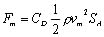 (7)
(7)
 (8)
(8)
So, the mean power, Wm(W) is calculated by the next equation.
 (9)
(9)
When the mean power, Wm(W) of Eq. (9) is smaller than the power of the motor, the motor keeps to drive the tail fin with stable motion.
A Design Flowchart for Reduced Ratio
We can predict the torque and power with the above equations, and adopt specifications of the fish robot approximately. However, in the first design stage, we must decide the reduced ratio of the gear mechanism. As an example, we introduce a design flowchart for the reduced ratio.
In a catalog or an explanatory note of a R/C model motor, the specifications in the maximum power condition, the maximum efficiency condition and no-load condition as shown in Table 1. Each rotating speed and torque satisfy the next relations, with the rotating speed (Hz), fP (the maximum power condition), fE (the maximum efficiency condition) and fN (the no-load condition), and the torque, TqP (the maximum power condition), TqE (the maximum efficiency condition) and TqN (the no-load condition).
 (10)
(10)
 (11)
(11)
When the torque decreases with increasing of the rotating speed in a line, the speed at the maximum power, fP equals to 1/2 of fN. Also, in the case of the R/C model motor, fE is very higher than fP, and is near fN. When such motor is adopted to a fish robot, the reduced ratio, D must be desided in the rated operation, that is in from fP to fE of the motor speed.
The relation between the frequency of the tail fin, f and the rotating speed of the motor, fmot(Hz) is f=Dfmot. Then the next equations are lead.
 (12)
(12)
 (13)
(13)
On the other hand, the related equations between Tqmot, fmot, r, A, SA and D with Eqs. (3)-(7). An example is the next equation.
 (14)
(14)
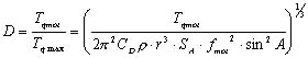
From Eq. (13), the next equation is lead.
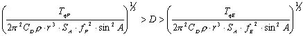 (15)
(15)
Table 2 lists the calculated results of the reduced ratio, D based on the size of the UPF-2001 (r=0.152 mÅCSA=0.036 m2) and the amplitude, A=10 deg. From this table, it was clalifed that 1/40 to 1/60 of the reduced ratio, D is suitable for the UPF-2001. After conciderations of the calculated results and location of the gears, we decided D=1/40.5.
Table 2. Calculated result for the reduced ratio
Click figure, show a bigger one.
Calculated Result
Figure 8 shows the calculated results of the relation between the frequency, f and the maximum torque, Tqmax. Also the torque of the final shaft with D=1/40.5 is shown in the figure. From the figure, Tqmax increases strongly with inclreasing of the frequency and the amplitude. In the figure, when the Tqmax is smaller than the torque of the final shaft, the motor can drive the tail fin.
Figure 9 shows the calculated results of the relation between the frequency, f and the mean power, Wm. As the same of Fig. 8, Wm increases strongly with inclreasing of the frequency and the amplitude. Also, when the Wm is smaller than the motor power, the motor can drive the tail fin suitably.
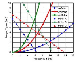
Fig. 8. Relation between the frequency and torque
|
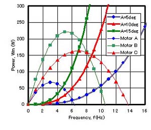
Fig. 9. Relation between the frequency and power
|
From these calculated results, we consider that High torque type motor, Motor B (Tamiya, ACTO-POWER) is effective in the condition of bigger amplitude, high speed type motor, Motor C (Tamiya, DYNA-RUN) is effective in the condition of high frequency and smaller amplitude. And we think that the standard motor, Motor A (Mabuchi, RS-540SH) is effective a long-time operation, because it has small consumer energy.
Conclusion
In this web page, we introduced the power unit of the UPF-2001 and the simple method for the mechanical design. In the above calculation, the tail fin is replaced to a flat plate. However, the real fin has cone-shape, so it may be that the drag coeffcient is diffrent from the above calculation. Also, we wonder that the constant drag coefficient is suitable or not, because the swimming fish robot has a complex water flow. However we sure that the qualitative characteristics of the torque and the power, as shown in Eqs. (5) and (8), are suitable for the mechanical design.
[UPF-2001]
[Experimental Fish Robots]
[ Fish Robot Home Page ]
[ Power and Energy Engineering Division ]
[ Hirata HOME ]
[ NMRI HOME ]
|