| "Dry Land" Fish Robot, Prototype PPF-01 October 21, Koichi Hirata 
"Dry Land" Fish Robot, Prototype PPF-01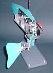
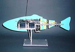 Our "Dry Land" Fish Robot, Prototype PPF-01, was built to prove out the mechanical design and control systems and was never water proofed. It was never intended to be put in water and was built prior to fish robot PF-600.
PPF-01 is controlled by a two-channel radio control (R/C) device. The photos to the right show the four skeletal parts of the fish: body, two peduncles and the tail. Each part is connected to the next by a single axis articulated joint. The R/C receiver, two servomotors (servos), servo cranks, and push rod linkages complete the prototype. The prototype was mounted on a stand that allows the whole system to freely rotate and move about on the table. This configuration allows study of the moments and dynamics of the system. It is as close as the PPF-01 will ever get to actually swimming.
Target goals for building PPF-01 were: Link Mechanism
Detail (a) shows the mechanism for joint 1. When the crank radius of servo 1 and servo 2 are the same, the angle at joint 1 is also the same. Detail (b) shows the mechanism for joint 2. When crank 1B, crank 2B and link No.2 are set as shown in this detail, the phase of the crank 2B equals to servo 1. Detail (c) shows details of joint 3. The angle at the joint 3 equals to the angle set by servo 2.
[ Power and Energy Engineering Division ] [ Hirata HOME ] [ NMRI HOME ] |
| Contact khirata@nmri.go.jp |
 The figure to the right is a schematic of the link mechanism adopted in the PPF-01. In this mechanism, the two servos move the three joints. Servo 1 moves joint numbers 1 and 2, and servo 2 moves the tail fin at the tail joint. Servo 1 is attached to channel 1 (Ch. 1) at the receiver, and servo 2 was connected to channel 2 (Ch. 2).