|
Study on Design and Performance Prediction Methods for Miniaturized Stirling Engine
Estimation of the engine performance

 Analysis model
In order to estimate the detail engine performance and discuss how to improve the engine performance, it is needed to predict both the indicated and shaft power accurately. Then, an accurate prediction of the indicated power is needed a matter of course, and also a mechanical loss of the piston mechanism and a buffer loss , which is complex thermal changes in the buffer space, must be estimated suitably. Especialy, the compact Stirling engine needs to have the buffer space as small as possible, in order to miniaturized the engine. Then it is impotant that the estimated method for the buffer loss, because the buffer loss becomes big and it affects the engine performance very much.
Belows analysis method considers the buffer loss, which has not been discussed until now. It is suitable for the compact Stirling engine.
 Working gas pressure
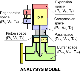 A right figure shows a analysis model of the prototype engine. A working gas pressure is calculated by an isothermal model, which separates five space. They are an expansion space including a heater space, a regenerator space, a compression space including a cooler space, a pass space and a power piston space.
As the thermal losses affected to the working gas pressure, a gas leakage from the piston ring and the rod seal, pressure losses in the heater, cooler and regenerator, and effects of sudden expansion and contraction flow in the regenerator are considered.
 Buffer pressure
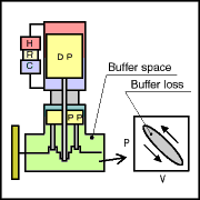 The buffer loss is a complex thermal loss in the buffer space, and is calculated by a buffer pressure changes and a buffer space volume changes.
A wall and gas temperature distributions become too complex, because there are many fever mechanical parts in the buffer space. So, it is too difficult to estimate the heat transfer of the buffer space accurately.
In this analysis method, the estimated method is discussed using three kind of methods, which are an isothermal, an adiabatic and a simple heat transfer models.
(1) Isothermal model
The buffer pressure can be calculated easily, under the assumption of constant gas temperature in the buffer space.
(2) Adiabatic model
The buffer pressure and gas temperature are calculated by solution of energy equations in the buffer space.
(3) Heat transfer model
As an assumption of the heat transfer model, the wall temperature in the buffer space is constant. And the buffer pressure and gas temperature are calculated bythe solution of the energy equations. The heat transfer is lead from an assumptive number of heat transfer unit, NTU.
 Mechanical loss
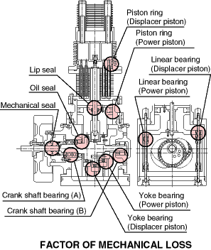 A right figure shows factors of the mechanical loss of the prototype engine. They are piston rings, a lip seal, an oil seal, a mechanical seal and bearings. This analysis model considers that the mechanical loss consists of a coulomb friction loss and a viscosity friction loss.
The coulomb friction loss is effected by only vertical force to the mechanical device. So, they can be lead easily by calculations of the mechanical forces.
On the other hand, the viscosity friction loss is effected by velocity of the device. So, it is very difficult to decide a viscosity coefficient analytical, because the loss is affected the temperature of the working device.
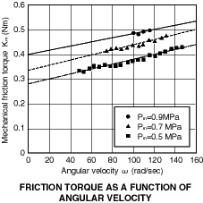 Then the viscosity coefficient has been lead by a previous experiment of the prototype engine. A right figure shows a relation between the angular velocity and the friction torque. These results show the viscosity coefficient is 9.0Å~10-4 Nms.
 Indicated power and shaft power
The indicated power is calculated by the working gas pressure. The shaft power is calculated by the indicated power, the buffer loss and the mechanical loss.
 Comparison of calculated and experimental results
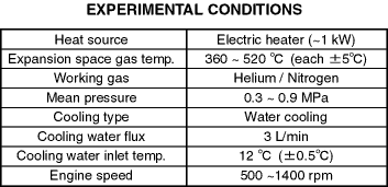 In order to verificate the analysis method, the prototype engine is experimenced with the experimental condition shown in a right table. As the working gas, helium and nitrogen are used.
 Buffer loss
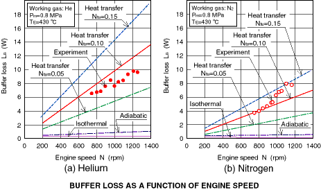
A belows figure shows the relation between the engine speed and the buffer space loss for both the calculation and the experiment. In this figure, the calculated results of the isothermal model and the adiabatic model were greatly smaller than the experiment results. On the other hand, the result of the heat transfer model corresponded with the experimental result, when the number of heat transfer unit, NTU was set to 0.1.
 Mechanical loss
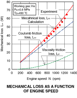 A right figure shows the relation between the engine speed and the mechanical loss. This figure shows that the calculation of the coulomb friction loss has a quadratic increasing to the engine speed. This means that there is few effect of piston inertia forces. As one can see from this figure, the mechanical loss can be simulated well, when the viscosity friction loss based the experimental result is considered.
 Indicated power and shaft power
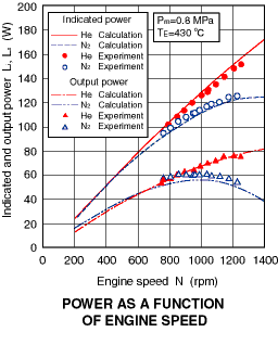 A right figure shows the relation between the engine speed and the indicated and shaft power. This figure shows the calculated results agree with the experimental result well. The indicated and shaft powers with nitrogen are larger than the powers obtained with helium greatly. It is considered that the cause was the large gas leakage from the piston ring and the lip seal mainly.
 Effects of gas leakage from seal device
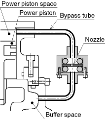 In order to discuss the performance of the seal device, the prototype engine is experimented using a valve between the working space and the buffer soace like a right figure. The performance of the seal device is adjusted by the valve diameter changes.
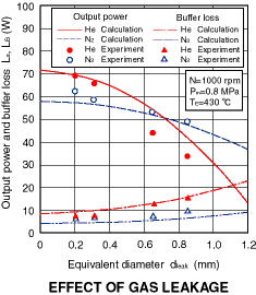 A right figure shows the relation between the equivalent diameter and the shaft power, the buffer loss at the engine speed, 1000 rpm. The equivalent diameter is lead from static tests of the prototype engine.
This figure shows that the power using helium is higher than that using nitrogen, when the equivalent diameter is smaller than about 0.7 mm. In the case of above experiment, the engine power using nitrogen was higher than that using helium. It is considered that the large gas leakage caused the characteristic of the prototype engine.
 Effects of buffer space volume
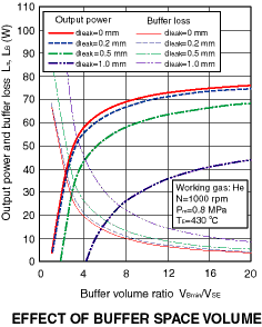 The prototype engine has the small buffer space volume compared with that of a general Stirling engine, because it designed as small as possible. It has a possibility to increase the buffer space loss.
A right figure shows the shaft power and the buffer space loss at 1000 rpm which were obtained with the volume of the buffer space. When helium is used, especially the power changes with the buffer space volume which influence the buffer space loss.
It was difficult to estimate of the buffer loss until now. I think that this analysis method is veru useful for the design of the compact Stirling engines, because the buffer loss and the mechanical loss are estimated easily.
 Conclusion
(1) The analysis model, which is considered the pressure loss at the regenerator, the gas leakage and the heat transfer in the buffer space was presented. It can simulate the engine performance adequately.
(2) The buffer loss of the prototype engine is estimated adequately, when it is considered the heat transfer with the number of heat transfer unit, NTU=0.1.
(3) The mechanical loss is estimated suitably with the assumption to consist of the coulomb friction loss and the viscosity friction loss.
|  Analysis model
 Working gas pressure
 Buffer pressure
 Mechanical loss
 Indicated power and shaft power
 Comparison of calculated and experimental results
 Buffer loss
 Mechanical loss
 Indicated power and shaft power
 Effects of gas leakage from seal device
 Effects of buffer space volume
 Conclusion
 A right figure shows a analysis model of the prototype engine. A working gas pressure is calculated by an isothermal model, which separates five space. They are an expansion space including a heater space, a regenerator space, a compression space including a cooler space, a pass space and a power piston space.
 The buffer loss is a complex thermal loss in the buffer space, and is calculated by a buffer pressure changes and a buffer space volume changes.
 A right figure shows factors of the mechanical loss of the prototype engine. They are piston rings, a lip seal, an oil seal, a mechanical seal and bearings. This analysis model considers that the mechanical loss consists of a coulomb friction loss and a viscosity friction loss.
  Then the viscosity coefficient has been lead by a previous experiment of the prototype engine. A right figure shows a relation between the angular velocity and the friction torque. These results show the viscosity coefficient is 9.0Å~10-4 Nms.
 In order to verificate the analysis method, the prototype engine is experimenced with the experimental condition shown in a right table. As the working gas, helium and nitrogen are used.
 A right figure shows the relation between the engine speed and the mechanical loss. This figure shows that the calculation of the coulomb friction loss has a quadratic increasing to the engine speed. This means that there is few effect of piston inertia forces. As one can see from this figure, the mechanical loss can be simulated well, when the viscosity friction loss based the experimental result is considered.
 A right figure shows the relation between the engine speed and the indicated and shaft power. This figure shows the calculated results agree with the experimental result well. The indicated and shaft powers with nitrogen are larger than the powers obtained with helium greatly. It is considered that the cause was the large gas leakage from the piston ring and the lip seal mainly.
 In order to discuss the performance of the seal device, the prototype engine is experimented using a valve between the working space and the buffer soace like a right figure. The performance of the seal device is adjusted by the valve diameter changes.
 A right figure shows the relation between the equivalent diameter and the shaft power, the buffer loss at the engine speed, 1000 rpm. The equivalent diameter is lead from static tests of the prototype engine.
 The prototype engine has the small buffer space volume compared with that of a general Stirling engine, because it designed as small as possible. It has a possibility to increase the buffer space loss.