|
Study on Design and Performance Prediction Methods for Miniaturized Stirling Engine
Proposal of a simple prediction method

 Proposal of a simple prediction method
In this session, a simple prediction method, which is used an early engine design process is proposed under the above experimental study.
It is impotant to predict the shaft power in the early engine design process. In such case, The method using Beale Number or West Number is used until now. As a problem of the method, the engine speed must be set for the calculation.
 About non-dimentional numbers
For more useful predicted method, it is noticed to find the relation between the engine speed and the shaft power. It becomes clearly how is the shaft power affected from the physical conditions by above analysis method and experimental results. After many discussions, the engine performance is affected by a shaft work, Ws, a mean pressure, Pm, a swept volume of the expansion space, VSE, a gas constant, R, gas teperatures, TE and TC, a viscosity coefficient, v and engine speed, n. It is desided that belows non-dimentional speed, n* and non-dimentional shaft work, wS* are used after a dimensional analysis.


On the other hand, as the non-dimentional numbers for the operating conditions, a permited pressure ratio, P* and a non-dimentional temperature, T* are defined.


 Relation between non-dimentional engine speed and shaft work
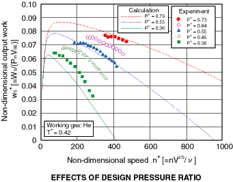 A right figure shows a sample of the relation between the non-dimentional speed, n* and the non-dimentional shaft work, wS*. It is confirmed that the experimental results can be reduced with n* and wS* very well.
 Proposal of performance prediction method
Under above results, non-dimentional shaft work, WS*, non-dimentional shaft power, LS* and non-dimentional engine specification, S* are defined as follows.


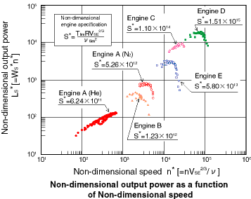 A right figure shows the relation between n* and Ls* with five kind of Stirling engines. Engine A is the prototype engine in this study. Engine B is an alpha-type Stirling engine with the same pewer level of Engine A. Engine C is a 2 kW class beta-type engine. Engine D is a 300 W class low temperature difference Stirling engine. And, Engine E is a 1 kW class low temperature difference Stirling engine.
This figure shows that there is the optimum value of Ls* on the each engines. And the optimum value, Lsmax* is related to n* and S*.
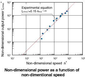 Next, a right figure shows the relation between nmax* and Lsmax* including experimental results of high performance Stirling engines developed in the world. From this figure, the relation between nmax* and Lsmax* is follows equation.

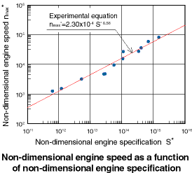 A right figure shows the relation between S* and Lsmax* including experimental results of the high performance Stirling engines. From this figure, the relation between S* and Lsmax* is follows equation.

 Flowchart for engine design
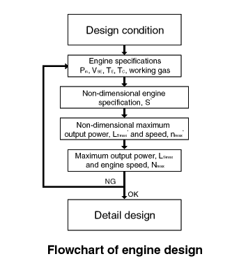 A flowchart for the engine design process is shown in a right figure. First, the engine specification is decided, and the non-dimentional engine specification, S* is calculated. Next, the maximum shaft power, LSmax and the optimum engine speed, Nmax are lead using above experimental equations. If the maximum shaft power and the optimum engine speed are enough performance, it is advanced to a detail design process.
 Conclusion
(1) A simple prediction method, which is used an early engine design process is proposed under the above experimental study.
(2) The method can predict the maximum shaft power and the optimum engine speed.
(3) The prediction method is suitable for the general Stirling engines, using the non-dimentional numbers, n*, LS* and S*.
|
 Proposal of a simple prediction method
  About non-dimentional numbers
 Relation between non-dimentional engine speed and shaft work
 Proposal of performance prediction method
 Flowchart for engine design
 Conclusion


 A right figure shows a sample of the relation between the non-dimentional speed, n* and the non-dimentional shaft work, wS*. It is confirmed that the experimental results can be reduced with n* and wS* very well.


 A right figure shows the relation between n* and Ls* with five kind of Stirling engines. Engine A is the prototype engine in this study. Engine B is an alpha-type Stirling engine with the same pewer level of Engine A. Engine C is a 2 kW class beta-type engine. Engine D is a 300 W class low temperature difference Stirling engine. And, Engine E is a 1 kW class low temperature difference Stirling engine.
 Next, a right figure shows the relation between nmax* and Lsmax* including experimental results of high performance Stirling engines developed in the world. From this figure, the relation between nmax* and Lsmax* is follows equation.
 A right figure shows the relation between S* and Lsmax* including experimental results of the high performance Stirling engines. From this figure, the relation between S* and Lsmax* is follows equation.
 A flowchart for the engine design process is shown in a right figure. First, the engine specification is decided, and the non-dimentional engine specification, S* is calculated. Next, the maximum shaft power, LSmax and the optimum engine speed, Nmax are lead using above experimental equations. If the maximum shaft power and the optimum engine speed are enough performance, it is advanced to a detail design process.