Tank Testing Technical Group
TANK TESTING
This group conducts experimental research to perform performance evaluation, which plays a crucial role in developing a ship shape with good propulsion performance and a propulsor (propulsion device). The "ship shape" includes not only the hull but also the rudder, keel, fins, etc.
Members
(◎: Head of the Group)
Main Research Theme
1. Propulsion Performance
When a ship tries to move, it receives resistance mainly from water (seawater). "Propulsion Performance" means the strength of the force required to overcome this and propel the ship. When a ship needs smaller propulsion force (for example, a ship of lower water resistance) than the same size ship at the same speed and with the same cargo, it is said to have better propulsion performance.
Traditionally, we have developed ships with good propulsion performance in the absence of waves, tidal currents, and wind (flat water). But in recent years, we have researched to develop a hull form of the ship with less resistance in waves and less horsepower or fuel consumption. Furthermore, ships are evaluated by not only propulsion performance but also comprehensive performance, including operation cost and ship price. Therefore, it is necessary to consider such propulsion performance during hull form development.
2. Propulsor
To drive the hull, a propulsion device (propulsor), which is the tire of a car, is required, and a well-known one is a screw propeller (usually called a propeller. In addition to the propeller, outer ring propeller, sail, etc. are also propulsor.).
In addition to the usual type of propellers that are often seen, there are various types of propellers: variable pitch propellers, duct propellers, contra-rotating propellers, and potted propellers currently talked about. They are chosen considering their respective advantages and characteristics.
3. Cavitation
To produce efficient propulsion (thrust) for the ship's advance, the pressure on the back (advancing) side of the propeller's blades drops to near vacuum. In such a low-pressure place, water boils even at room temperature (15℃), and bubbles form. This phenomenon is called cavitation. In the cavitation, when the bubbles collapse, high pressure occurs and damages the propeller and rudders. Also, noise occurs at this time. This noise becomes a problem for submarines and ships with acoustic sonar. Among problems caused by cavitation, the most important one is the vibration of the stern. This problem focuses on commercial vessels from the viewpoints of comfort and safety, and improving this occurrence prediction technology is most expected.
4. Evaluation of Ship Propulsion Performance and Tank Test
The propulsion performance of a ship with a hull shape is still basically evaluated in still water. Therefore, the performance of the full-scale ship is estimated through the performance measurement by towing the model ship in a large pool called a towing tank. This model test method was developed over 100 years ago, data has been accumulated, and the test method has been improved to this day. Our institute has two towing tanks. One is the "Mitaka No. 2 Ship Model Experiment Tank" (commonly called "large tank" or "400-m towing tank"). This tank is one of the world's hugest towing tanks and is 400m in length, 18m in width, and 8m in depth. The other is the "Mitaka No. 3 Ship Model Experiment Tank" (commonly called "150-m towing tank." This tank is 150m in length, 7.5m in width, and 3.5m in depth) and can also change the water depth. In addition, both can generate various waves. This feature enables us to research performance in waves assuming actual sea areas.
In addition to these tanks, we have a large cavitation tunnel to evaluate propulsion performance centering on the propulsor. Unlike the towing tank, this is a circulating tank in which water circulates inside the tank, and the tank inside can be decompressed to a near vacuum so that cavitation can occur. This facility is one of Japan's largest cavitation (circulating) water tanks, with a length of 16m and a height of 10m.
5. Development of Tank Test Method
This group is working on the development, improvement of accuracy, and efficiency of the tank test method to obtain more accurate resistance and propulsion performance of a ship, which are the basis of the hull form development. Regarding the tank test method, the International Towing Tank Conference (ITTC, an NGO) establishes a technical committee on the most advanced rational test methods to conduct research, investigation, discussion, and recommendation activities. Our institute (NMRI) participates in the ITTC as a member and participates in its Advisory Council that manages the conference. A few researchers are working in the council as technical committee members in each term to provide international cooperation and contribution.
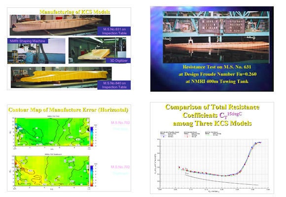
Fabrication of KCS model ship and dimension inspection (left)
Tank test of KCS model ship (right)
6. Hull Form Development
Conventional hull form development has been conducted by empirical manufacturers of many model ships to find a good hull form in a series of tests using a database that accumulates past test results, wave-making resistance theory, propeller theory, etc. On the other hand, many numerical calculation methods (NFD, including Computational Fluid Dynamics, CFD) have developed in response to the development of high-performance computers in recent years. Currently, the new method using NFD has been adopted. In this method, the optimum ship shape is searched by NFD before the tank test and finally confirmed by the tank test. To provide verification data for the reliability confirmation of CFD programs, this group conducts repeated tests for uncertainty analysis and transmits the obtained verification data to the world. Through these efforts, we plan to propose a hull form with excellent propulsive performance based on a new concept.
Overview of Research
1. Micro Bubble PIV (technology that "visualizes" the invisible flow)
"What are microbubbles?"
Due to the impact on the global environment, international regulations on ships are tightened. At NMRI, we are working on the research of eco-friendly vessels. In this research, the propulsive performance evaluation of vessels plays an important role. We would like to introduce a study called "Micro Bubble PIV" that makes the propulsion performance evaluation more accurate.
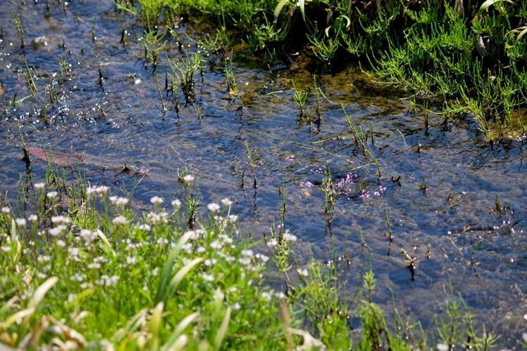
Everyone would have a desire to see the invisible world. For example, we can feel the flow of water and air outdoors, but we cannot understand where the flow is coming or going.
As a record of those who challenged this question, a sketch of the vortex flow around a flat plate placed in the stream (1513: below) drawn by Leonardo da Vinci is known as an old record. Another famous painting that depicts the flow of water in detail is "Madonna with St. Dominico, St. Peter, and St. Christopher." This fresco is displayed in the museum of the church of St. Dominico in Bologna, Italy. Prof. Mikio Hino pointed out in his book "Fluid Mechanics" that the vortex flow around the feet is drawn in detail.

Since ancient times, our ancestors have been aware that fallen leaves in a stream flow along a stream. And that movement can tell the direction and speed of the stream. An object that serves as a mark, such as a fallen leaf flowing in a stream, is called a tracer. Nowadays, we put substances such as fallen leaves in the flow to see the movement of the invisible flow. This method is called the tracer injection method.
The technique that makes the flow visible to the human eye in this way is called the "flow visualization technique."
Flow visualization technique was used for a long time in research dealing with various flows: flow around a ship hull, flow around a wing, flow in a pipe, etc. Using this technique, various new fluid phenomena, such as the transition from ordered flow (laminar flow) like comb teeth to turbulent flow like intertwined threads, can be found. In addition, researchers concerned with fluid flow are not satisfied with visualization techniques that only look at flows and have developed methods for calculating numerical values such as velocity and direction from flow images.
A typical example of these methods is PIV. PIV is an abbreviation for Particle Image Velocimetry. It is an application of the principle of judging the scale and direction of a stream from the motion of fallen leaves in a stream and smoke from a chimney in the wind. PIV was developed as a quantitative visualization technology. In this method, the computer is used instead of the human eyes to obtain the flow direction and velocity reasonably and efficiently with less error.
Here, we would like to explain how the procedure is taken in PIV. First, we take images of the flow field continuously. Then, choose two pictures taken at different times (Fig.1). Comparing the first (right) and second (left) images, you can see that the green object is moving to the right on the second image. You can only know the direction and amount of movement from two images, but if you know the time interval between two images, you can find the speed.
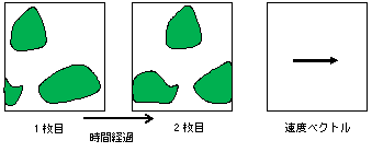
Fig.1 Principle of PIV Measurement
Incidentally, in recent years, from the viewpoint of global environmental protection, the requirement to tighten international environmental regulations for ships has been increasing. Ships should decrease fuel consumption as much as possible to reduce carbon dioxide emissions from ships. Many efforts are being made around the world to improve fuel efficiency by improving the propulsion performance of ships that push water away. To this end, it is crucial to investigate the water flow around the vessel that impedes the ship's forward movement and to design as efficient a ship as possible.
NMRI is also working on research to reduce carbon dioxide emissions from ships. This group is developing technology to evaluate the propulsive performance of a ship by measuring the flow around the ship in detail using PIV, one of the quantitative visualization techniques described above.
We often use a fine powder as a tracer for PIV measurement in experimental water tanks. They are particles having a specific gravity close to water, such as silver-coated hollow glass beads (Fig. 2) and nylon particles.
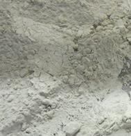
Fig.2 Silver-coated Hollow Glass Beads
However, it is practically hard to collect the powder once sprinkled in the aquarium for visualization. As a result, it will contaminate the water in the experimental aquarium. It limited us to using PIV easily.
"Watching the flow with micro bubbles"
To solve this problem, we are developing a method by using very minute air bubbles (microbubbles) as tracers that do not remain in the aquarium, unlike the powder tracer.
Microbubbles used here are bubbles with a diameter of 50 μm (0.05 mm) or less and smaller than the diameter of the hair. The bubbles you see in ciders and baths will float quickly. But microbubbles are so minute that they do not float immediately. Also, when you look at the photo in which the generated bubbles exist in the beaker, it looks white and cloudy, as shown in Figure 3 (left). If you expand it, you can see minute bubbles, as shown in Figure 3 (right).
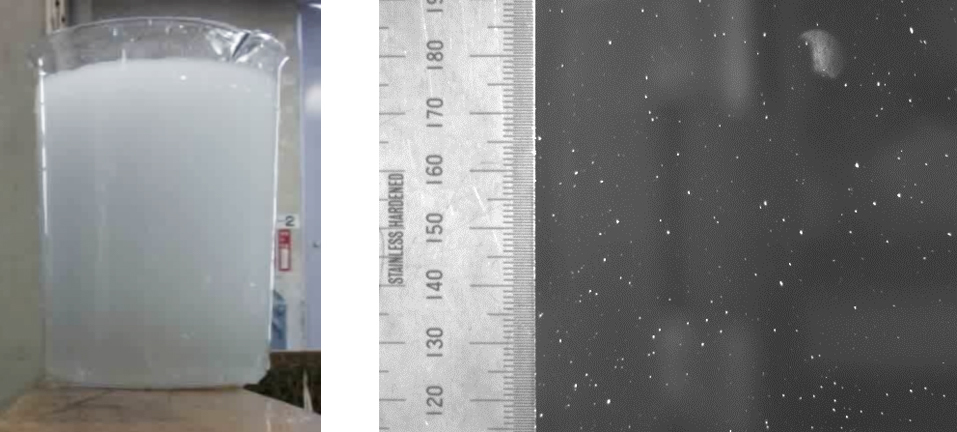
Fig.3 Microbubbles (left: Turbid microbubbles. right: Enlarged photo. White particles are microbubbles)
Here, we show an example of a measurement result using a microbubble as a tracer. Figure 4 shows the flow field in sinusoidal waves generated in the oscillation tank.
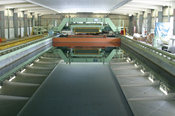
Fig.4 Oscilation tank
Below the movie (Fig.5) is an actual image of sinusoidal waves generated in the oscillation tank. White dots are microbubbles.
Fig.5 Image of sine wave flow field
From this movie, you can see that the microbubbles draw a circular motion in water. When the velocity was calculated from this image and compared with the theoretical value, it was found that there was a good agreement, as shown in Fig.6. In the future, we plan to improve the measuring device to measure the flow around the model ship.
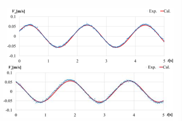
Fig.6 Measurement result and theoretical profile
Red: Theory, Blue: Measurement (Good agreement can be found)
2. Utilization of 3D printer for tank test
To increase the propulsive energy efficiency of ships, we attempt to improve the flow field around the vessels by attaching additional objects, such as protrusions and cylinders, to the hull and to decrease fuel consumption. Some recent ships have ducts or fins attached to the hull to improve performance. These objects are called energy-saving devices.
Our department is conducting tests to confirm the effects of these devices. We must manufacture them to exact dimensions for evaluating their effect precisely by tank tests. Furthermore, we must mount them at the precise position. Therefore, we sometimes needed to make special jigs for alignment. It takes a lot of time to make them. To conduct evaluation tests efficiently, we required a new tool to shorten the preparation of the tests. In this situation, the 3D printer attracted our attention.
In recent years, 3D printers have become more accurate in manufacturing and cheaper. In addition to the attached objects, we can manufacture jigs and reference fittings used for alignment with sufficient accuracy by 3D printers. Now, we can conduct tank tests more efficiently than ever using the 3D printer.
Here, we show you some objects made by 3D printers.
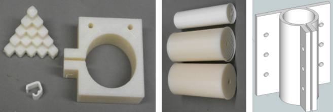
Fig.7 Objects manufactured by the 3D printer (left)
and an example of a CAD drawing for manufacturing with a 3D printer (right)
- Read 3D CAD data.
- Convert it to a file format for a 3D printer.
- Transfers it to the 3D printer.
