Research Overview
Research Overview
Research on Motion Reduction Technology for Underwater Linear Structures
For underwater linear structures like riser pipes, the motion of the upper floating structure and vibrations caused by tidal currents can lead to significant fatigue damage. These vibrations must be considered in the design. Consequently, the connection between the upper floating structure and the underwater linear structure is often equipped with a mechanism called a ball joint or bend stiffener to reduce the bending moment at the end. Additionally, a chain suspension mechanism is used at the connection to release the bending moment in suspended structures. This study investigated a method to suppress the vibration of the entire pipe by placing a damping mechanism in the middle section of the underwater linear structure, especially at the flange connecting the pipe to the pipe.
For the vibration control mechanism, we created a model, as shown in Figure 1, based on the seismic isolation mechanism of buildings and placed this model between pipe models simulating steel pipes. We conducted the model test in the Deep Sea Basin at NMRI, where the upper floating structure was subjected to forced horizontal displacement using a forced exciter at the top end. We measured the behavior of the pipe model under the assumption that the upper floating structure was in motion. Figure 2 shows the water basin test at that time. Based on the measurement results of the basin tests, we conducted numerical simulations using OrcaFlex, a commercial software program widely used in marine development, to verify the effectiveness of the vibration control mechanism.
Figure 3 shows a comparison of amplitude distribution as an example of the results of a top-end forced excitation test. The amplitude is non-dimensionalized by dividing it by the upper-end excitation amplitude. The amplitude was the largest in the case without the vibration control mechanism, followed by the laminated rubber, spring, and damper, respectivaly. The damper type, which had the greatest amplitude reduction, showed an amplitude reduction effect of up to 40% compared to the case without the vibration control mechanism. Figure 4 shows a comparison of numerical simulation results and basin test results. We obtained approximate agreement between the numerical simulation and the basin test results for the cases without and with a damper-type damping mechanism installed at the fixed top end. The numerical simulation of the bending moment distribution showed that in the case of the fixed top end, not only did the moment escape at the position where we installed the damping mechanism, but the bending moment also reduced further down the pipe and at the top-end connection.
This research was financially supported by JSPS Grant-in-Aid 26630461.
For details of this research, please refer to the paper published in JMST (Journal of Marine Science and Technology) in 2024. (
![]() download
)
download
)
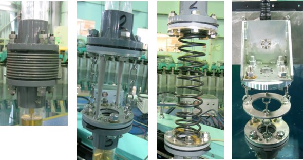
Figure 1 Vibration-damping mechanism model and chain suspension model
(from left to right: laminated rubber type, damper type, spring type, and chain suspension device (*1))
(*1) Patent No. 5665024 "Riser Pipe Suspension Device and Mooring Pipe Connection Device"
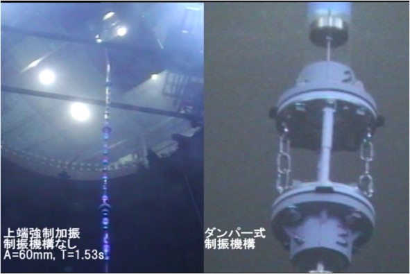
Figure 2 Water basin test
(left: Overview, right: Damper-type vibration damping mechanism connected to riser pipe model)
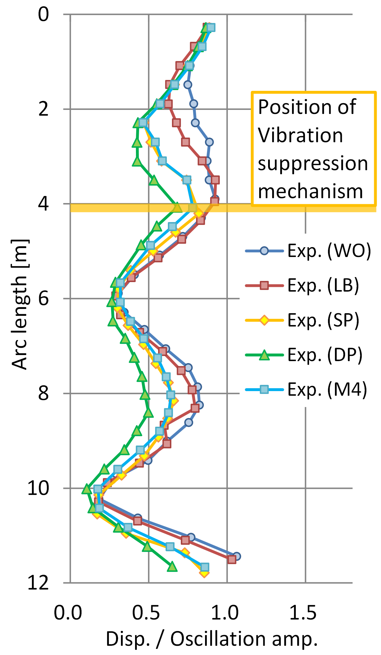
Figure 3 Top-end forced vibration test results
(Vibration period: 5sec, amplitude: 0.5m)
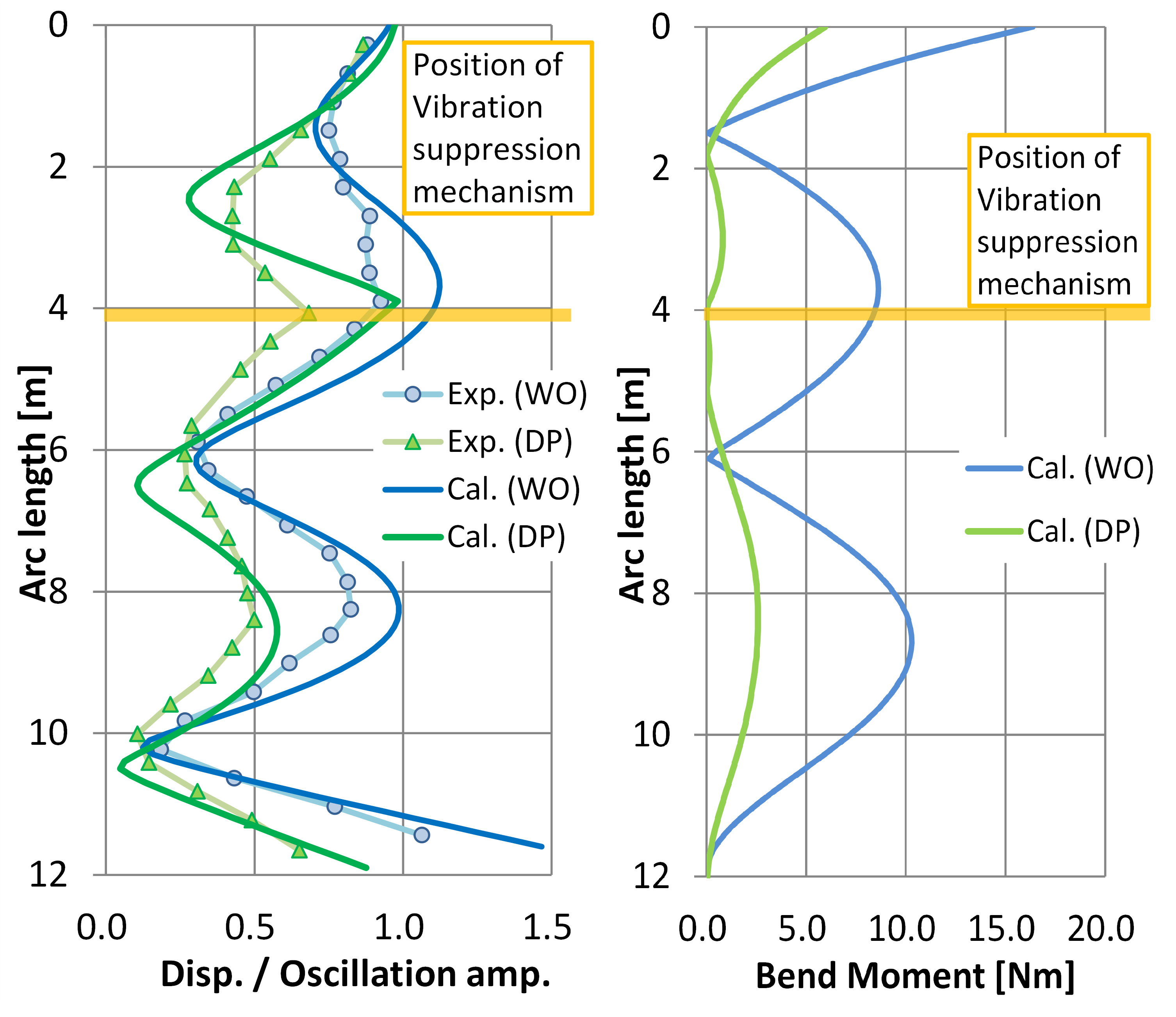
Figure 4 Comparison of numerical simulation results and basin test results
(left: Amplitude distribution, right: Bending moment distribution)