Measurement of electric power of the PPF-04
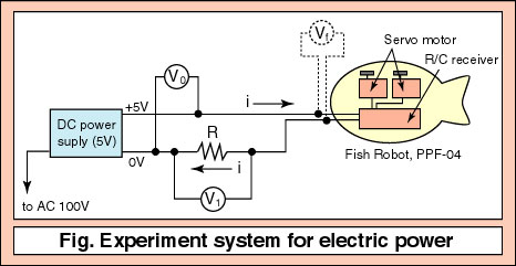
Measuring system for the erectric powerA belows figure shows an experimental system for the electric power of the PPF-04. It consists of an electric source, V0 (=5 V), a resistance, R (=0.67 ohm). The resistance is located between the electric source and a R/C receiver. When a voltage at both ends of the resistance, R, is V1 (V), an electric current, i (A) is calclated by;i=V1/R A voltage at the R/C receiver, Vf (V) is; Vf=V0-V1 Also, an electric current in the fish robot (R/C receiver) equals to the electric current through the resistance, R. So, the electric power in the fish robot, We (W) is; We=Vfi=(V0-V1)V1/R Namely, when the V0 and V1 are measured, the electric power, We is led. In this experiments, in order to be stable, a AC-DC converter (5V, 5A) is used instead of the NiCd battery (7.2V, 110mAh). Also, the voltage, Vf and the electric current, i change always by the motion of the servo motors. So, the Vf and i are taken averages using a A/D converter (sampling frequency, 1kHz and 1000 data). In the case of the more detail experiments, it is needed to adjust the sampling time properly.
Effects of the frequency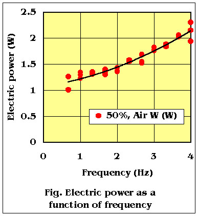 A right figure shows a relation between the electric power and the frequency at outside of the water. The operating condition is that phase angle, 90 degrees, the maximum amplitude is each 20 degrees from the center line. This result shows the electric power increases to the higher frequency.
When switch on the R/C transmitter and receiver, and the servo motors are not moded, the electric power is 1.32 W (average of five times). The electric power for the servo motor motion under the lower frequency is very a few, because the electric power, 1.32 W is used for receiving the radio wave. When switch off the R/C transmitter, the electric power is only 0.18 W. There is a big difference of the power at switch on and off. It is caused by the noise of the transmitter.
CommentIt is made sure that the electric power can be measured by the above method. But I think that more high accuracy is needed in detail experiments.
 Video of the PPF-04 Turning performance of the PPF-04 Relation between the speed and frequency Relation between the speed and phase angle [ View of Model Fish Robots ] [ Fish Robot Home Page ] [ Power and Energy Engineering Division ] [ Hirata HOME ] [ NMRI HOME ] |
| Contact khirata@nmri.go.jp |
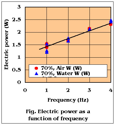 A right figure shows a relation between the electric power and the frequency at outside of the water, and in the water. The operating condition is that phase angle, 90 degrees, the maximum amplitude is each 30 degrees from the center line. This results show that their electric power is equal approximately. The difference of the power in the water and that of outside is the power which is used to push the water. But it has not been able to measure, because it is too small. The same results are gotten when the amplitude is 20 and 40 degrees.
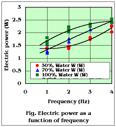 A right figure shows a relation between the electric power and the frequency in the water. The operating condition is that phase angle, 90 degrees, the maximum amplitude is each 20, 30 and 40 degrees from the center line. These results show that the electric power increase to the bigger amplitude. When the maximum amplitude is set to 40 degrees, the power is measured somewhat small at the hjgh frequency. The reason is that the motion of the servo motor cannot overtake to the high frequency, because the voltage of the R/C receiver is low.
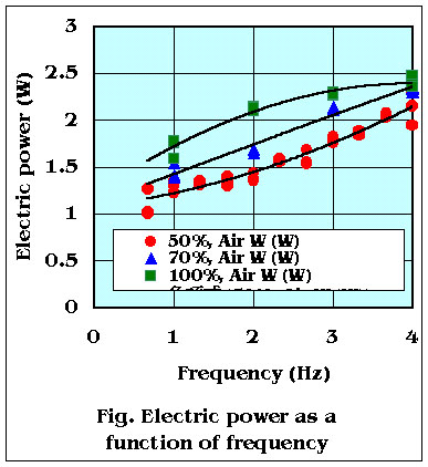 A right figure shows a relation between the electric power and the frequency at outside of the water. The operating condition is that phase angle, 90 degrees, the maximum amplitude is each 20, 30 and 40 degrees from the center line. These results show the same in the water.
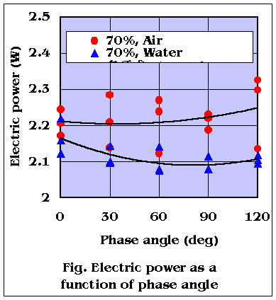 A right figure shows a relation between the electric power and the phase angle at outside of the water, and in the water. The maximum amplitude is each 30 degrees from the center line. This results show that the electric power does not change to the phase angle at the outside of the water, though the experimental data is scattered. On the other hand, in the case of the operation in the water, the electric power increases to the smaller phase angle. The reason is that the power to push the water increases to the smaller phase angle.