Research Facilities
RESEARCH FACILITIES
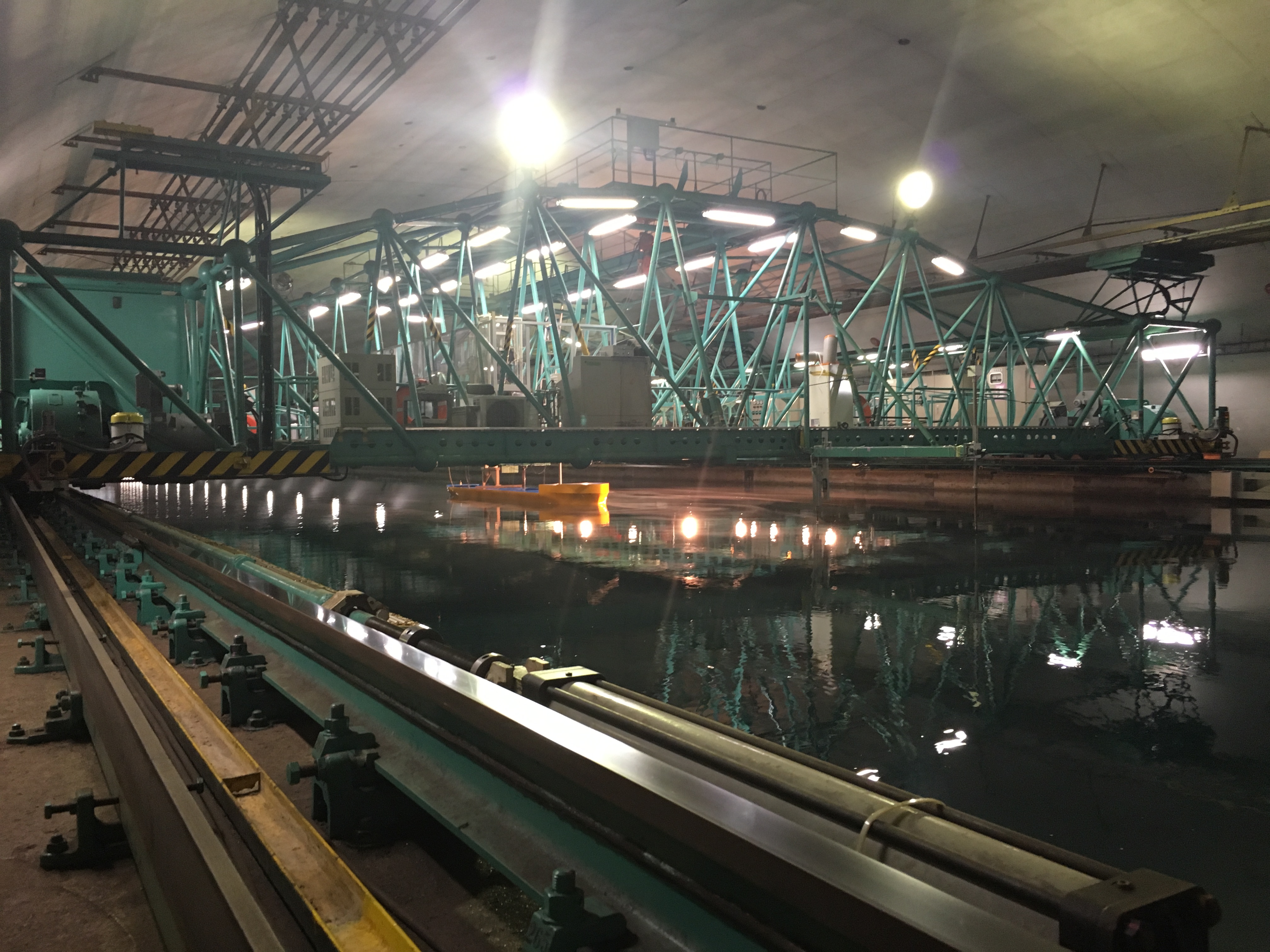
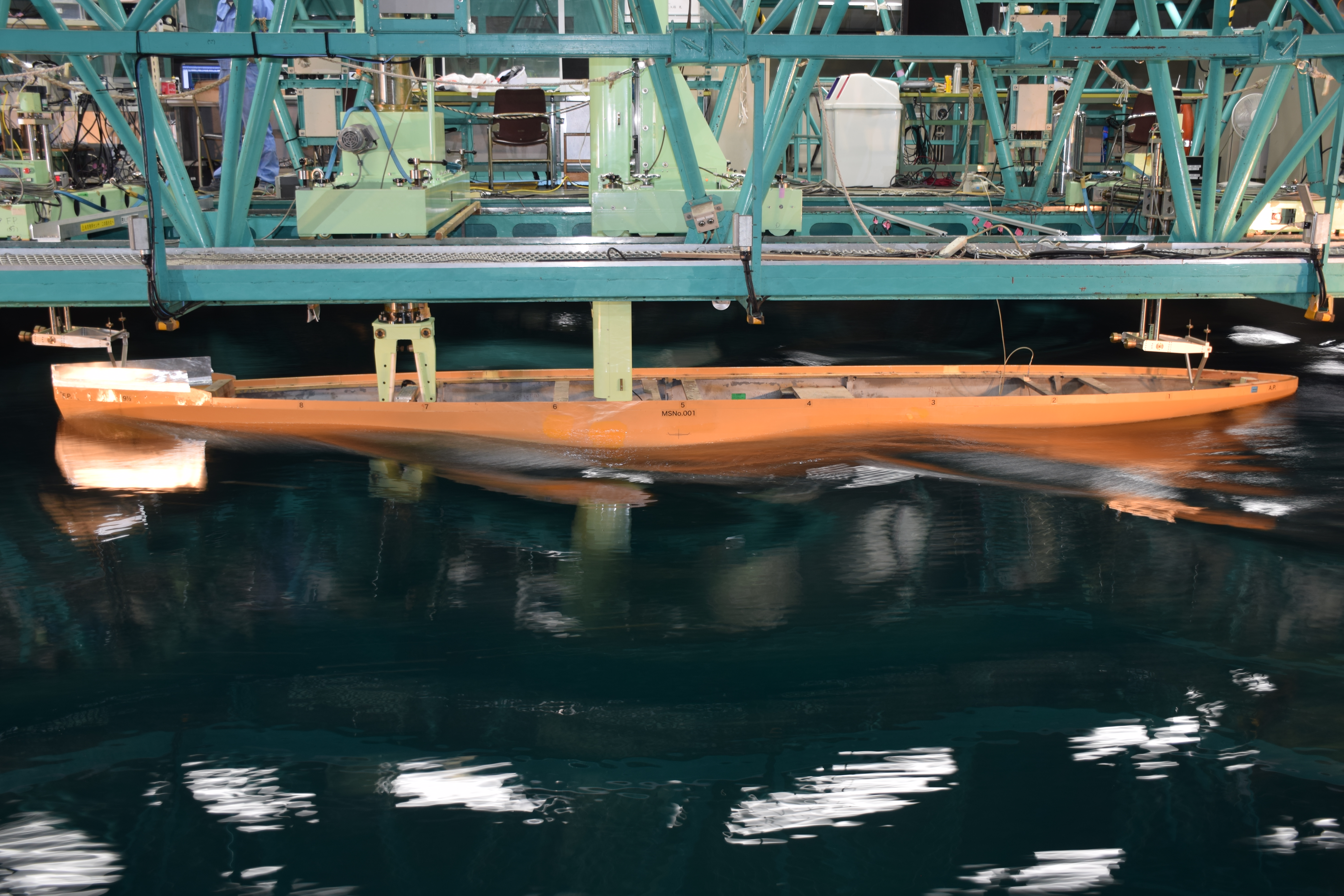
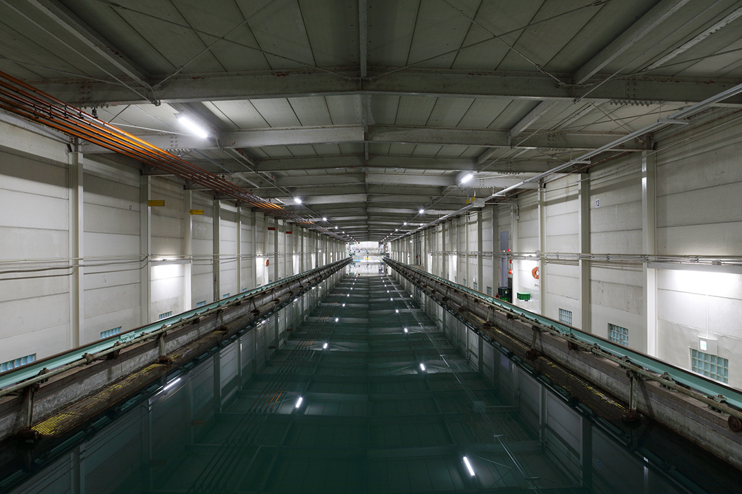
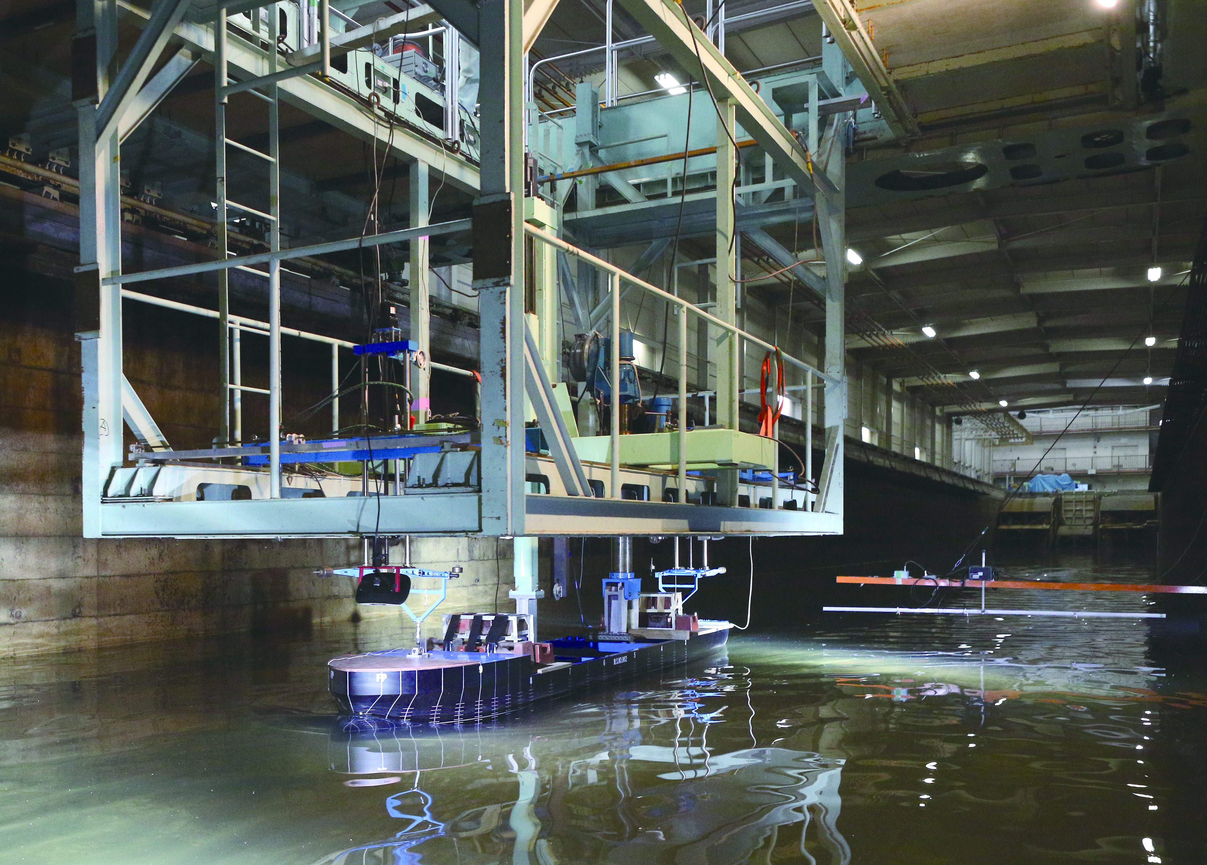
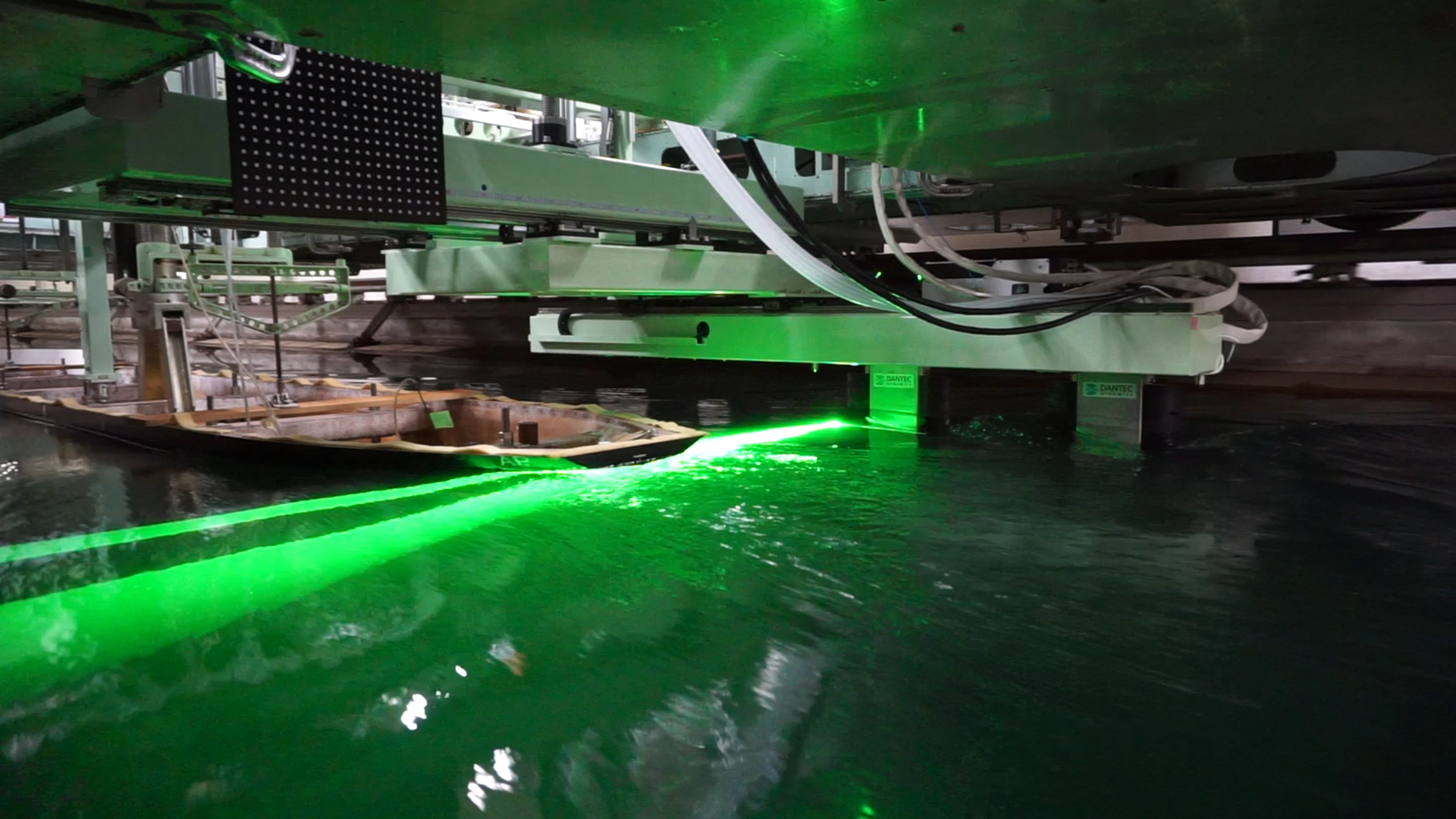
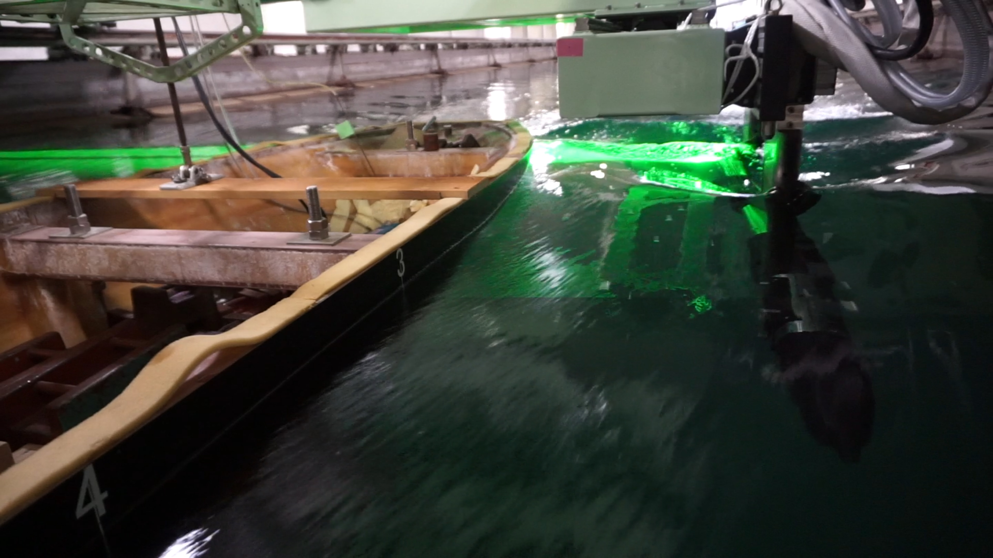
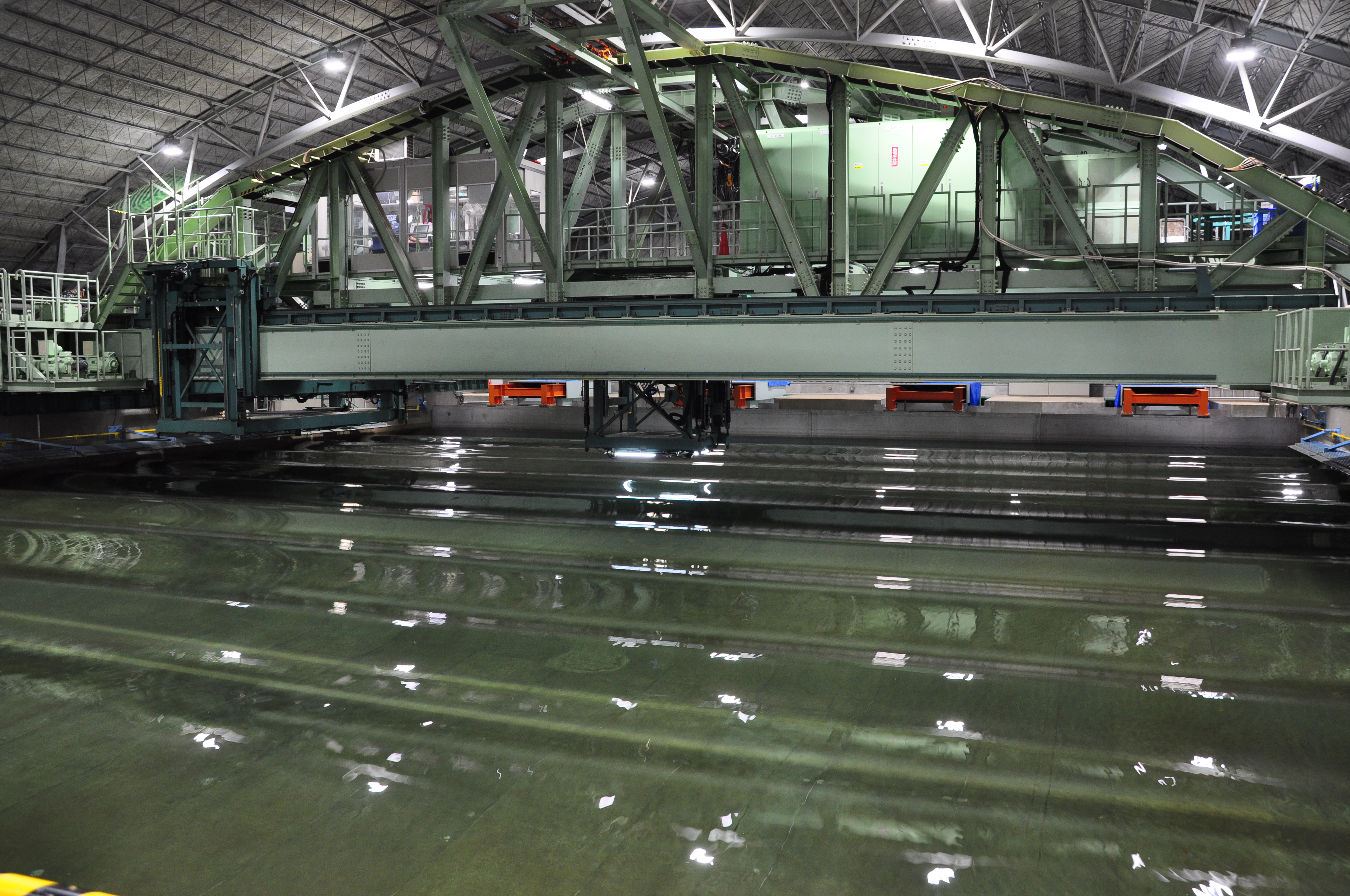
400-m Towing Tank (Mitaka No. 2 Ship Model Experiment Tank)
Completed: 1966
Tank dimensions: 400.275 m (L) x 18 m (W) x 8.1 m (D), the largest cross- sectional area (width and depth) in the world, enabling highly accurate measurements.
Towing carriage: Maximum speed of 15 m/s (54 km/h), the fastest in Japan for testing commercial ships
Wave generator: Separated plunger type; wavelength 0.5 to 15 m; maximum wave height of 0.3 m
Sub-carriage: It can be connected to the towing carriage
Click the image to enlarge it
400-m Towing Tank is one of the world’s largest towing tanks capable of performing model tests for high-speed ships and large-scale model ships. It is used mainly for resistance and self-propulsion tests. ISO9001 certification for “propulsive performance tests” has been obtained for the purpose of improving the quality of tank tests.
Also, maneuverability tests and tests in waves can be performed.
Applications:
The following tests can be performed:
- Tank tests necessary for EEDI regulations enforced to reduce greenhouse gas emissions- resistance and propulsive performance tests
- Tank tests in regular head waves necessary for acquiring the EEDIweather certification
- Tank tests for evaluating the effects of hull form optimization and energy-saving device to improve EEDI/EEDIweather
* EEDI: Energy Efficiency Design Index (enforced on January 1, 2013)
** EEDIweather: Energy Efficiency Design Index considering weather effect (starting from January 1, 2013)
Recent achievements:
- Performing of tank tests necessary for acquiring the EEDI/EEDIweather certifications
- Research and development of energy-saving equipment (WAD, etc.)
- Performing of tank tests to evaluate the effects of air lubrication to reduce skin-friction drag by towing a model ship having an overall length of 50 m, and the results led to the technology being implemented in the full-scale ships
Recent research:
- Evaluation of the resistance and propulsive performance of ships with different drafts and trims; development of energy-saving hull forms and devices; development of the air lubrication method; development of energy-saving hull forms for domestic ships and the evaluation; measurement of stern flow fields by PIV using microbubbles as tracers
* PIV: Particle Image Velocimetry, a method for measuring the flow rate by imaging a flow field with tracers distributed in fluid and analyzing the captured images
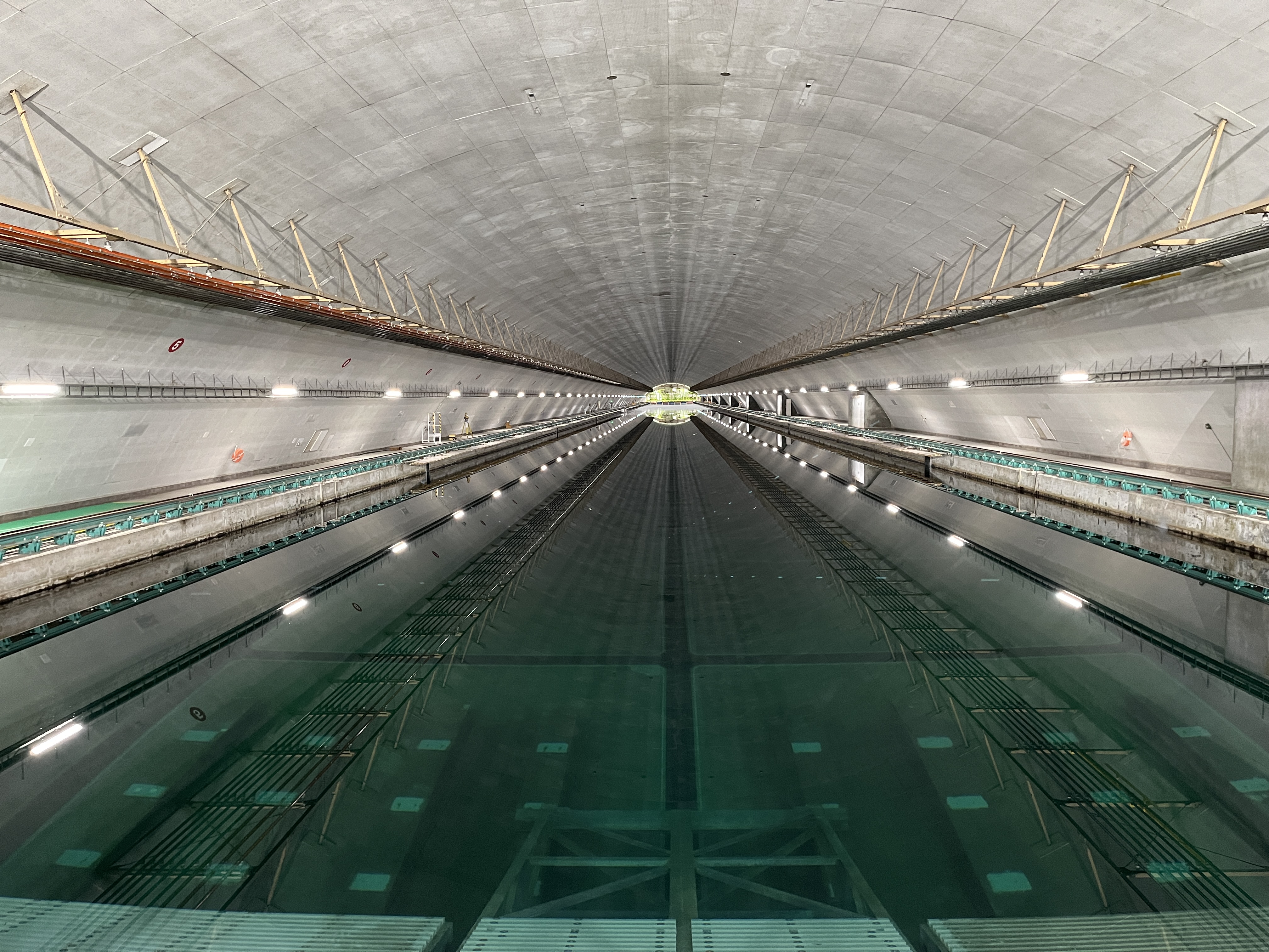
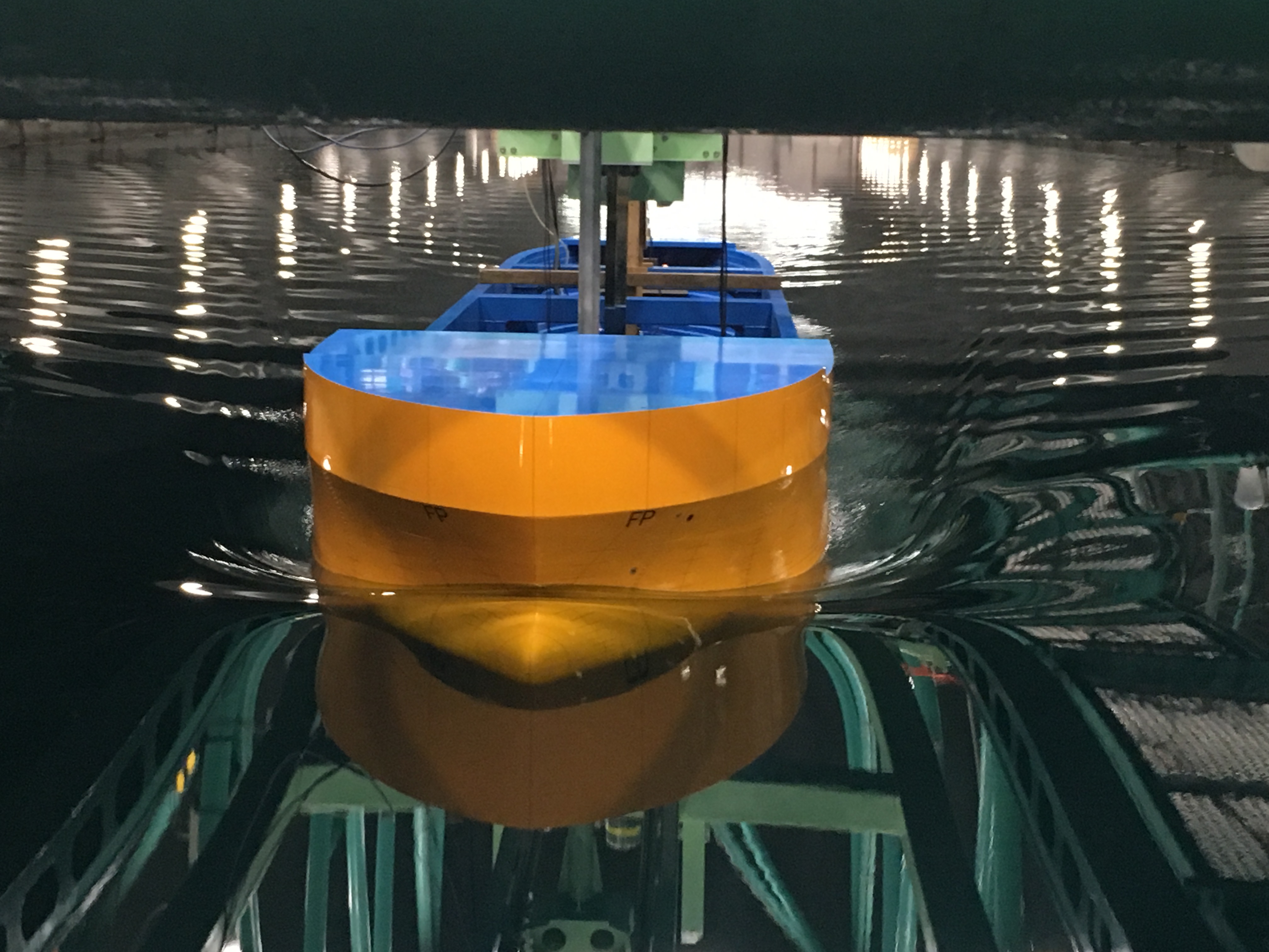
150-m Towing Tank (Mitaka No. 3 Ship Model Experiment Tank)
Completed: 1971
Tank dimensions: 150 m (L) x 7.5 m (W) x 0 to 3.5 m (D, variable)
Towing carriage: Maximum speed of 6 m/s
Wave generator: Separated plunger type; wavelength 0.5 to 10 m; maximum wave height of 0.3 m
Click the image to enlarge it
150-m Towing Tank can perform tests that simulate both deep and shallow waters. It can be used as a multipurpose tank for resistance and self-propulsion tests, tests in waves, tests for evaluating the friction resistance by ship paint, measurement of stern flow fields through PIV, and more. ISO9001 certification for “propulsive performance tests” has been obtained for the purpose of improving the quality of tank tests.
Applications:
The following tests can be performed:
- Resistance and propulsive performance tests
- Tank tests in head waves
- Tank tests for evaluating the effects of hull form optimization and energy-saving device
- Measurement of flow fields by PIV
Recent achievements:
- First in the world to perform the EEDIweather certification test
- Research and development of energy-saving device for reduction of added resistance in waves (STEP, etc.)
- Performing of tests for evaluating the friction resistance by ship paint with high precision friction resistance dynamometer
- Contributions to international standard on the shallow water correction method through deep water/shallow water tests
Recent research:
- Evaluation of the resistance and propulsive performance of ships in waves with different drafts and trims; Research and development of energy-saving hull forms and devices for the reduction of added resistance in waves; Measurement of stern flow fields by PIV
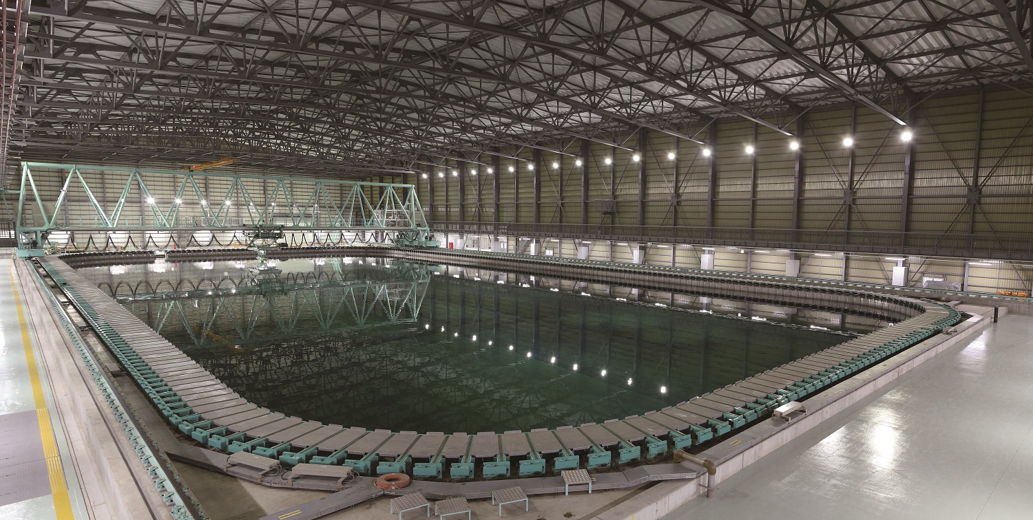
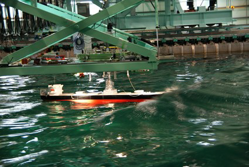
Actual Sea Model Basin
Completed: 2010
80 m (L) x 40 m (W) x 4.5 m (D)
All-round separated absorbing-type wave generator: 382 units
Blowers
X-Y-Ψ towing carriage system with main carriage (longitudinal X direction), sub carriage (transverse Y direction) and turntable (ψ direction around vertical axis)
Click the image to enlarge it
In this basin, waves and winds encountered in the actual sea can be reproduced with its all-round wave generators and blowers.
Applications:
- Investigation of causes of maritime accidents and prevention measures to them
- Development of hull forms with high energy-saving performance through accurate estimation of ship motion in the actual sea
Recent achievements:
- Model experiments reproducing an accident of a fast ferry with heeling to a large extent , accidents of fishing vessels with broaching and capsizing, etc.
- Sophistication of wave making technology for rogue waves, etc.; development of efficient seakeeping test method with utilizing multi-directional regular waves
- Development of a test method for directly estimating actual sea performance of ships through free-running model tests
Recent research:
- Estimation of the actual sea performance of ships
- Development of energy-saving hull forms and devices
- Risk assessment for parametric rolling, etc.
- Estimation and evaluation of maneuverability under waves and winds
- Development of wave and wind power generation facilities
- Estimation of wave loads using elastic type ship models
Ocean Engineering Basin
Completed: 1977
Full-scale renewal of the towing carriage: 1996
Water tank: 44.5 m (L) x 27.1 m (W) x 2.0 m (max. D)
Towing carriage: The maximum speed of the main carriage is 0.7 m/s, the maximum speed of the running sub carriage is 0.5 m/s, the fixed sub carriage can be moved to any position, and both sub carriages can be moved up and down.
Wave generator: Piston type capable of making regular and irregular waves; period of 0.5 to 3.0 seconds; maximum wave height of 0.6 m
Current generator: Maximum flow rate of 0.3 m/s
Wind generator: Maximum wind speed of 12 m/s for the horizontal arrangement type and 10 m/s for the rectangular arrangement type
Click the image to enlarge it
This basin is a large rectangular basin in which model tests can be conducted under the combined external forces of wind, waves and currents. Also, this basin has a variable water depth, making it possible to conduct model tests for shallow water areas (the only one in Japan).
Applications:
- This basin can be used for elemental tests such as fluid force measurement tests and maneuverability tests, in addition to general tests for general commercial ship, dedicated ships, and offshore structures.
- Implementation of research and development to disseminate and promote floating-type offshore wind power generation facilities; implementation of safety evaluation tests to realize offshore operations such as production, offloading and bunkering of next-generation fuel
Recent achievements:
- Evaluation of wave-induced coupled dynamics between multi-purpose offshore supply vessel and suspended load during crane lifting operation
- Establishment of a mooring safety evaluation method for floating-type offshore wind power generation facilities
- Evaluation of slewing motion of single point moored hull
- Development of technology for testing the motion of two ship hulls on open waters while taking into consideration the influence of the sloshing of on-board tanks designed for offshore transportation of LNG related to LNG bunkering, FLNG, etc.
- Development of technology for testing the motion of ships moored to quay walls/berths on open waters
- Development of technology for evaluating the safety of DPS
- Development of control technology related to autopilot for ships
- Establishment of a method for investigating and estimating the VIM characteristics of spars and subsea equipment
- Clarification of the behavior of mooring lines on rogue waves
Recent research:
- Motion analysis for crew transfer vessel pushing its bow against offshore wind tower during transfer operation
- Evaluation of maneuvering hydrodynamic forces at low speeds and large drift angles for estimating slewing motion during tandem offloading
- Evaluation of mooring line tension for slewing motion under the initial stage of dragging anchor
- Development of an active method for experiment of model including mooring line
- Development of a method for evaluating the operability and safety of offshore LNG transportation and LNG transportation with ships berthed at quay walls
- Research on the evaluation of safety during a crane operation in ocean
- Research on the development of fundamental technologies and safety evaluation methods for offshore renewable energy
- Research on the clarification of the VIM phenomenon and an evaluation method for semisubmersible floating bodies
- Verification of a fracture accident involving a semisubmersible mooring line presumably due to rogue waves and viscous drift force
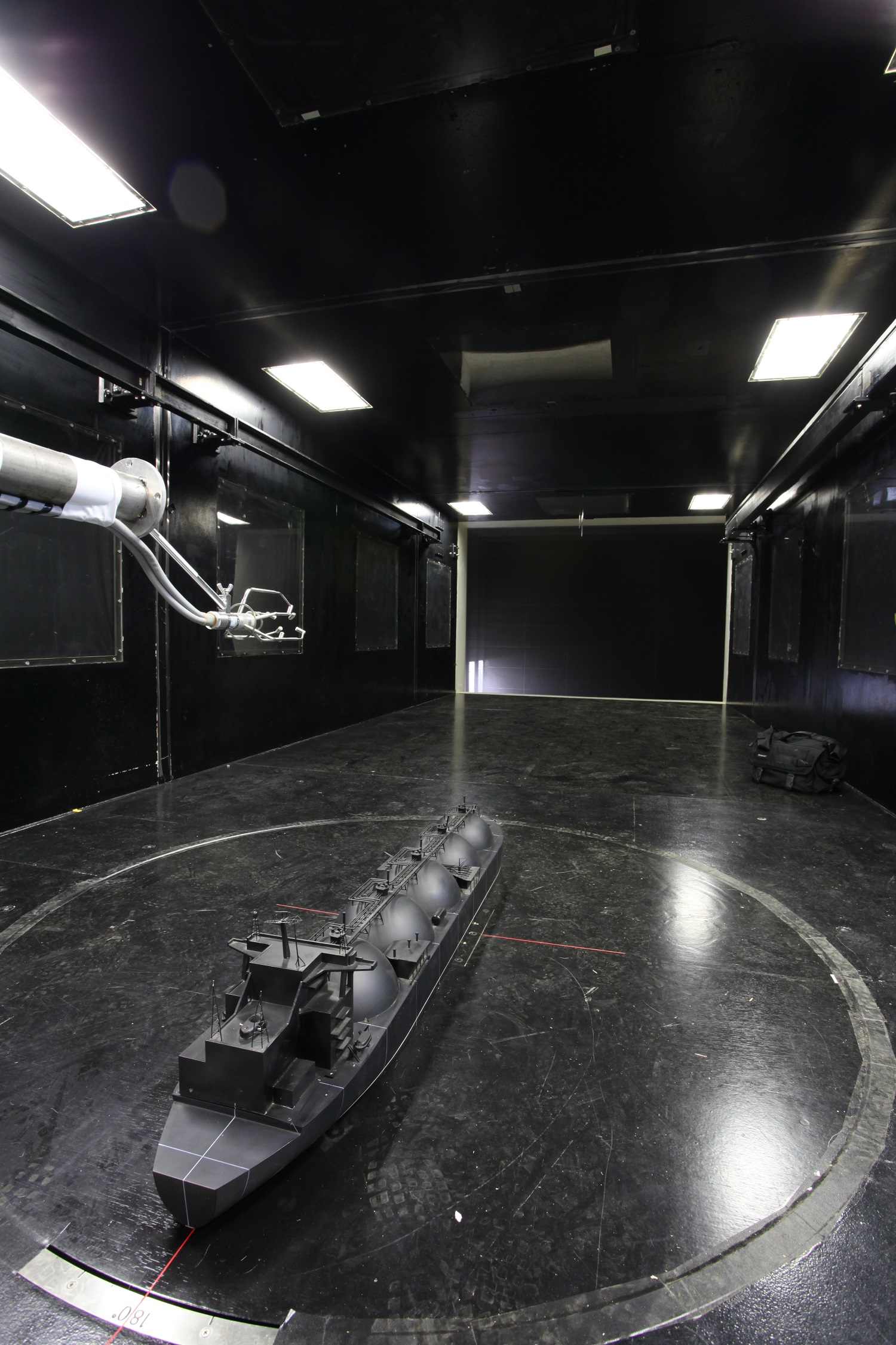
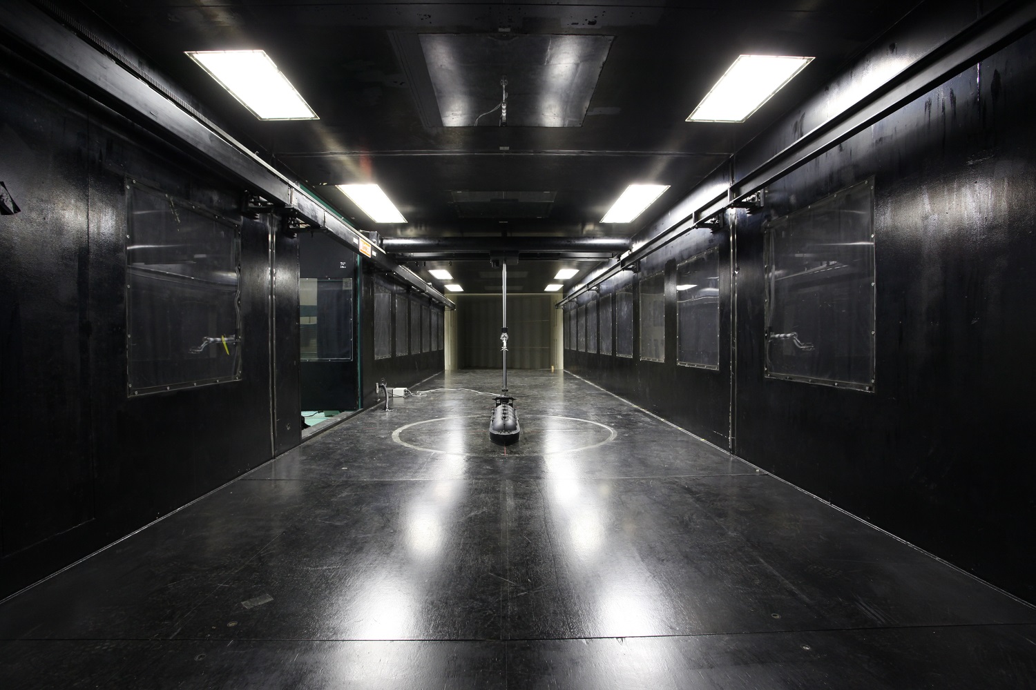
Pulsating Wind Tunnel with Water Tank
Completed: 1993
Wind tunnel section: Goettingen-type horizontal circuit; capable of generating sinusoidally fluctuating wind
Closed type: 15 m (L) x 3 m (W) x 2 m (H); wind speed of 1 to 30 m/s
Open type: 3 m (L) x 3 m (W) x 2 m (H); wind speed of 1 to 30 m/s
Water tank section: 15 m (L) x 3 m (W) x 1.5 m (D)
Wave generator: Regular and irregular waves; flap type
Maximum wave height of 0.3 m; period of 0.6 to 4.0 seconds
Other items: Traverse device, turning table, 6-axis load cell, etc.
Click the image to enlarge it
The behavior of ships and offshore structures in high quality wind, waves and current can be measured. This facility has a removable floor to conduct just wind tunnel tests without a water tank. It is possible to reproduce ocean conditions and measure the behavior of ships and offshore structures, focusing on wind characteristics. In such cases, wind load on the conventional ships, offshore structures, and high-speed vessels, and visualization of wind flow around structures can be conducted.
Applications:
- Safety evaluation of ships and offshore structures in wind and wave environments
- Evaluation of wind resistance characteristics for the development of shapes for ships, offshore structures, and high-speed vessels.
- Evaluation of blade pitch control performance of floating offshore wind turbines.
- Safety evaluation of gas leakage around floating structures.
Recent achievements:
- Measurement of wind pressure characteristics of ships and offshore structures
- Mooring Safety Assessment of Floating Offshore Wind Turbines
- Development of blade pitch control algorithm for floating offshore wind turbines and measurement of mooring line tension
- Measurement of leaking gas concentration from gas tanks of LNG carriers
Recent research:
- Research on evaluation of ship navigation performance
- Research on safety assessment of offshore structures
- Research on the development of basic technologies and safety assessment methods for offshore renewable energy systems
Deep Sea Basin
Completed: 2002
Maximum water depth: 35 m; upper section: diameter of 14 m, depth of 5 m
Pit section: Diameter of 6 m; depth of 30 m
Active Absorbing Wave Generator - Flap Type Snake System:
Current Generator:
・Wave Period: 0.5 - 4.0 sec Max. Wave Height: 0.5 m (2.0 sec)
・Max. Flow Velocity Upper (circular basin) 0.30 m/s
・Lower (deep pit) 0.15 m/s
Underwater 3-D Measurement System: 36 units
Click the image to enlarge it
One of the world’s deepest model basins
Capable of artificially generating various waves, wind, and currents
Applications:
Contribution to the development of deep-sea petroleum gas extraction and the establishment of utilization technologies for seabed minerals in Japan’s EEZ
Recent achievements:
- Establishment of technologies for evaluating the behavior of lifting tubes to develop submarine hydrothermal deposits
Recent research:
- Research on slurry transport to develop seabed minerals
High Pressure Tank
Completed: 2002
Inner diameter: 1.1 m; height: 3.0 m
Pressure: Maximum pressure 60 MPa
Flow generator: Maximum flow velocity 0.1 m/s
Cooling unit: Controlling water temperature in tank in the range of 2℃ to room temperature
pH controlling unit: Controlling water temperature in tank in the range of pH 5 to 11
Other items: Underwater cameras, lights and a thermometer in the tank
Click the image to enlarge it
Capable of reproducing deep-sea pressure environments up to water depth of 6,000 m
Capable of real-time monitoring inside the tank
Applications:
- Pressure test of pressure vessels used under deep sea conditions
- Operation test of deep sea equipment at high pressures
- Visual observation of objects at high pressures
Recent achievements:
- Research on processing of seabed minerals
- Development of a subsea machine for testing element technologies to excavate seafloor massive sulfides
Recent research:
- Research on slurry transport to develop seabed minerals
Introduction Movie :
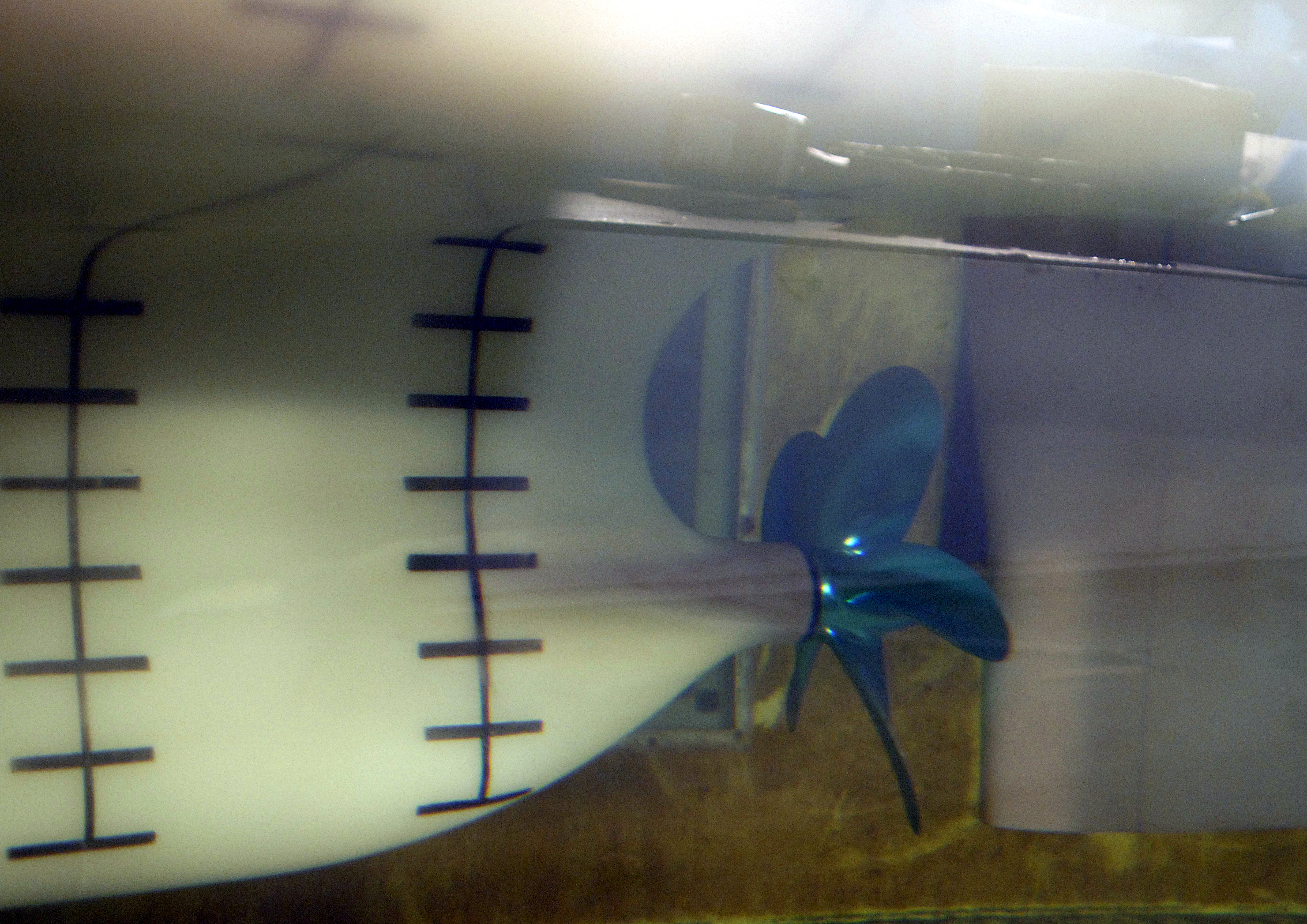
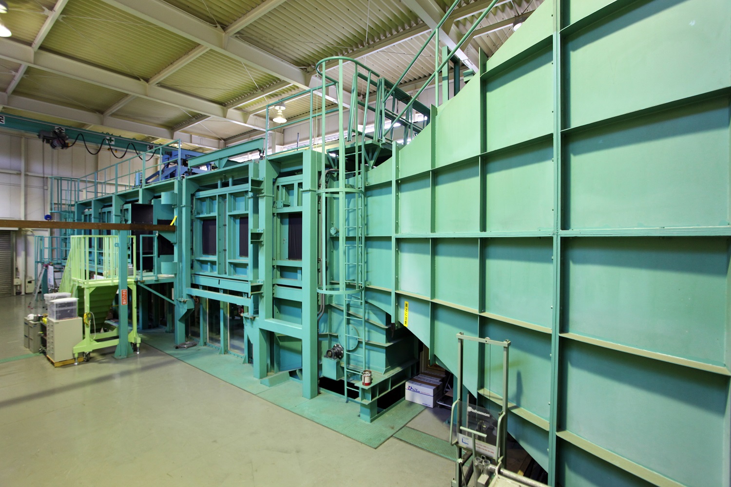
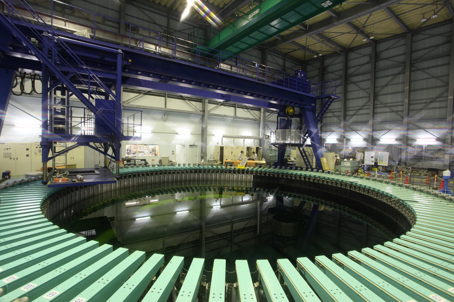
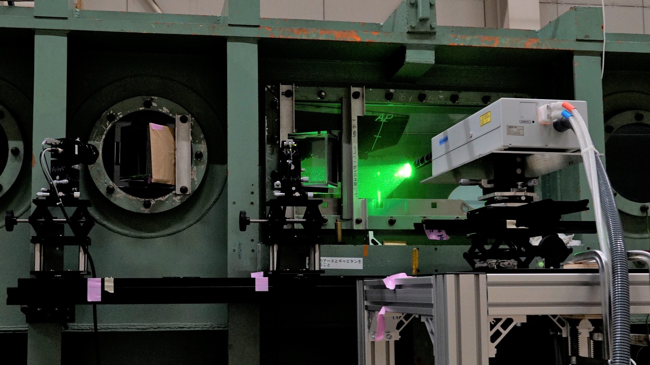
Large Cavitation Tunnel
Completed: 1975
Overall length of 18 m; height of 10 m
Type: Vertical closed-type variable-pressure circulating water tunnel; pressure range 5 to 200 kPa
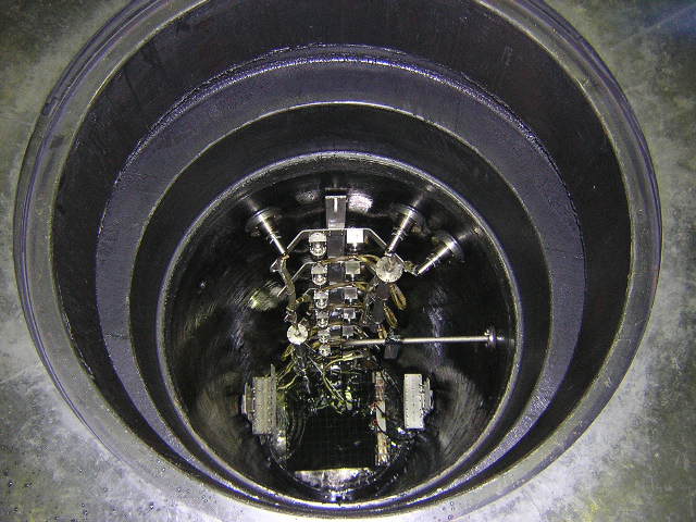
No. 1 working section: Length of 2.25 m; circular cross section of 0.75 m diameter; maximum flow velocity of 20 m/s; maximum propeller diameter of 400 mm
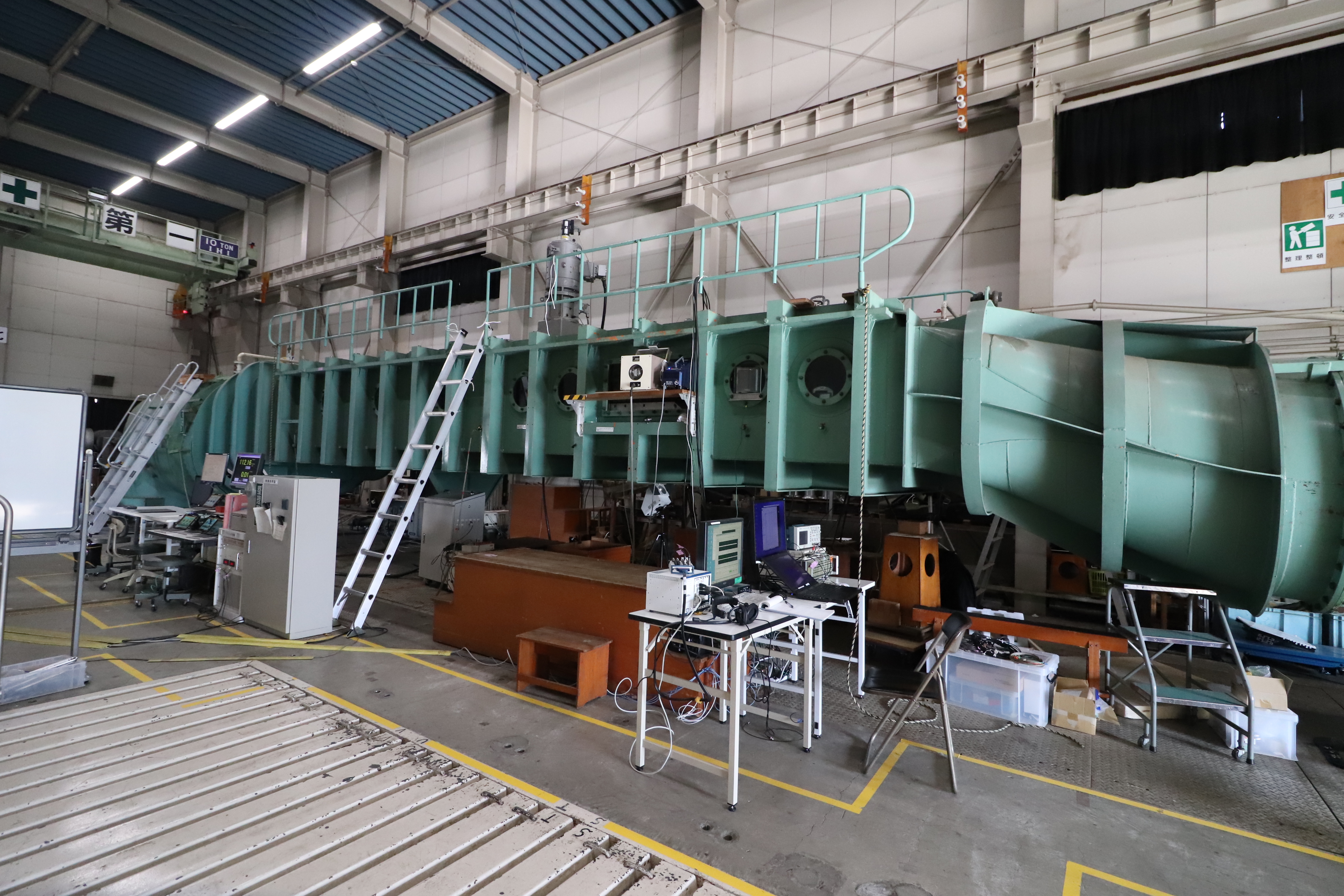
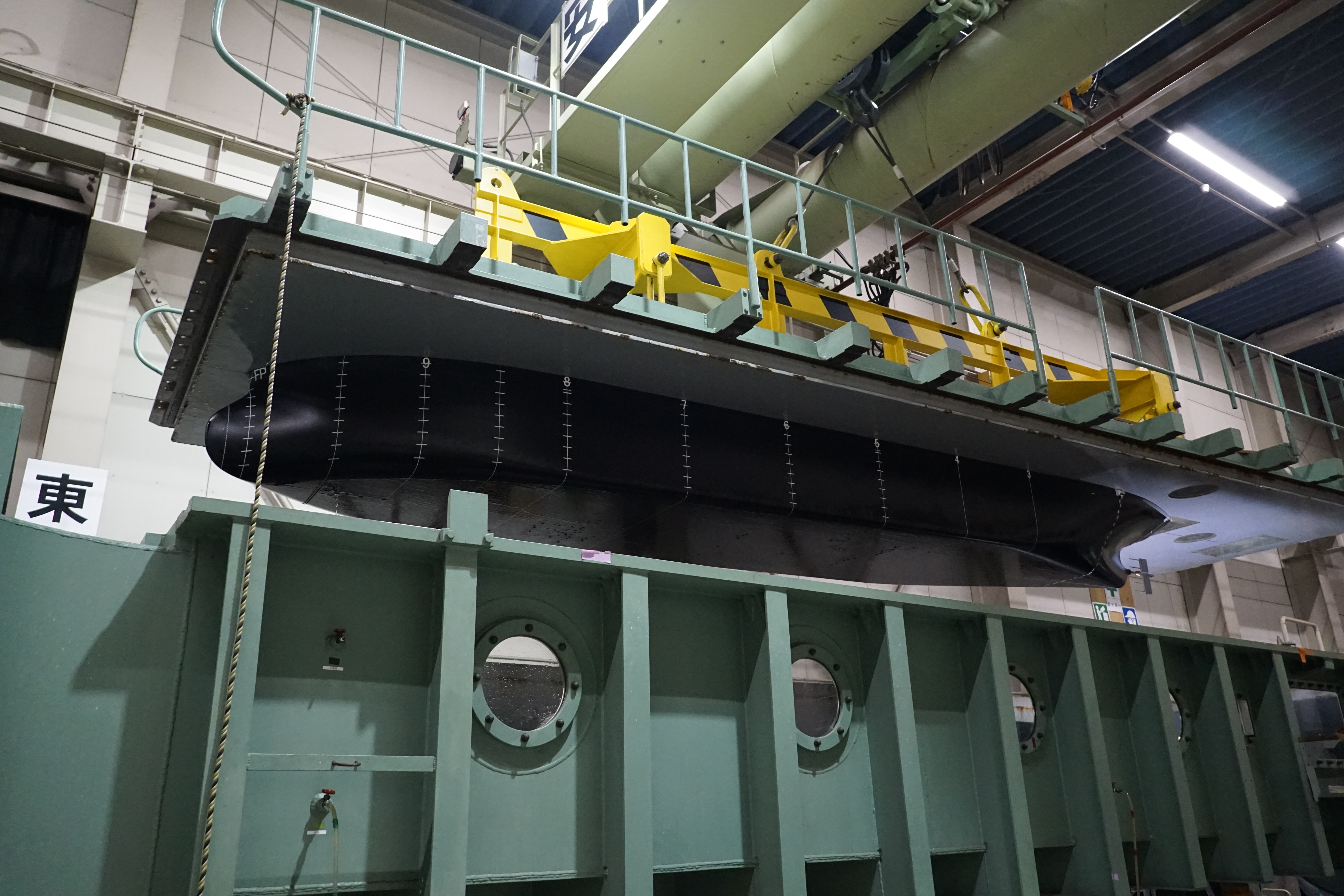
No. 2 working section: Length of 8 m; rectangular cross section of 2 m x 0.88 m; maximum flow velocity of 6.5 m/s; maximum model ship length of 7 m
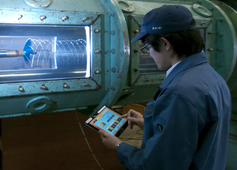
Click the image to enlarge it
Large Cavitation Tunnel can be performed: Cavitation tests for propellers that simulate the cavitation number of full-scale ships in a sealed-type water tunnel with a decompression function; Detailed flow field measurement using LDV/PIV and visualization of flows. ISO9001 certification for “propulsive performance tests” has been obtained for the purpose of improving the quality of tank tests.
No. 1 working section is used for model propellers, rudders, and blades.
No. 2 working section is used for the measurement of fluctuating pressure at the stern by cavitation tests with a model ship set in the section.
* Cavitation: A physical phenomenon in which bubbles are generated and vanish in a short period due to pressure differences inside fluid. Cavitation is known to occur on the surfaces of propeller blades due to their rotation. Cavitation causes efficiency reduction, vibration, noise, and erosion of the blades.
Applications:
The following tests can be performed:
- Measurement of the propeller cavitation phenomenon to develop propellers that prevent cavitation and erosion as well as reduce vibration and noise
- Evaluating cavitation performance while considering the influences of interference with energy-saving device (WAD, etc.) at high rate of propeller revolution close to that of full-scale ship
- Research and development of super-cavitating propellers that utilize the cavitation phenomenon to improve the efficiency of propellers at high rate of propeller revolution
Recent achievements:
- Creation of the guidance of calculation of the equivalent rudder area for high lift rudders under the minimum propulsion power to maintain the maneuverability of ships in adverse conditions through the tank tests
- Development of a non-contact measurement system of the cavitation volume on a propeller blade
- Development of a measurement system of the deformation of an elastic propeller during rotation
- Performing of tests for the deliberation of international standard of the underwater noise measurement method
- Round-robin tests of model propellers with major EU research institutes and these evaluation.
* Minimum propulsion power to maintain the maneuverability of ships in adverse conditions:
A regulation that requires ships to be equipped with main engines having the minimum propulsion power to maintain a certain level of maneuverability even in rough seas for the purpose of preventing accidents such as grounding, etc. along with enforcement of the EEDI (Energy Efficiency Design Index) regulation
Recent research:
- Assessment of the relation between cavitation volume and fluctuating pressure
- Measurement of the deformation during rotation of composite material propellers
- Measurement of the underwater noise by propellers using the model ship
- Assessment on the cavitation by WAD
- Measurement of surface roughness in the boundary layer with LDV using a large flat plate
- Detailed measurement using PIV of flow fields interfere with propellers and energy-saving devices at the stern
* Boundary layer: A region formed in an area close to an object’s surface due to the viscosity of fluid that has a slower speed than that of the fluid
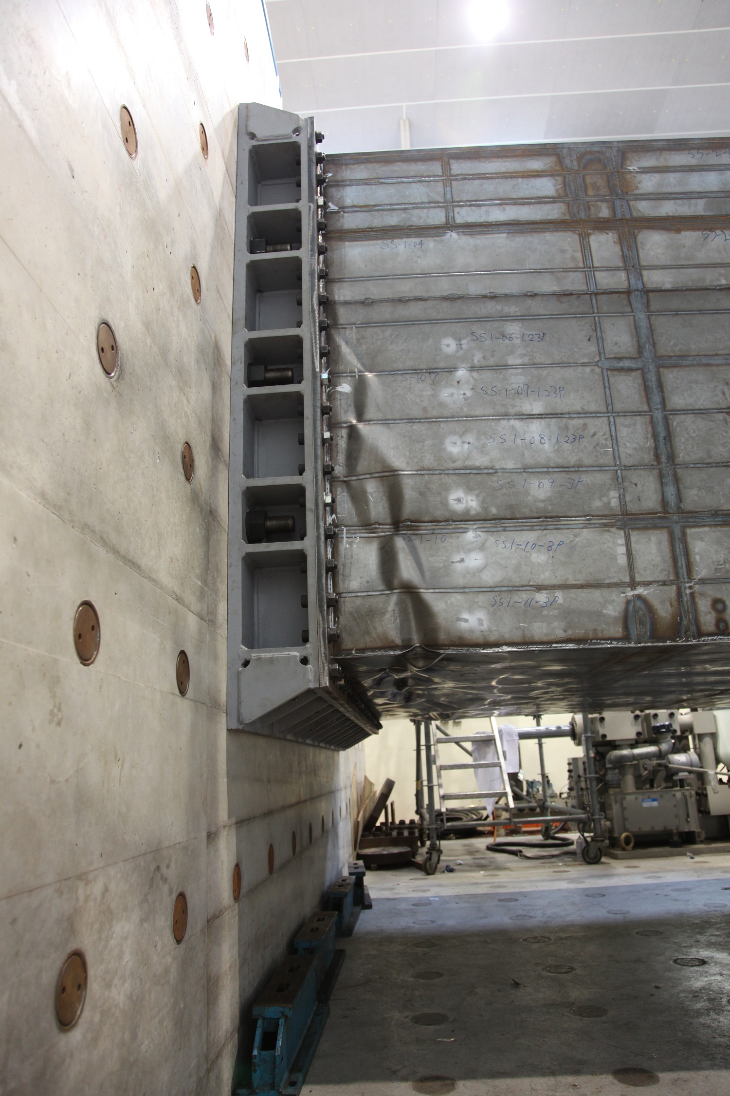
Multi Axis Loading System
Completed: 1995
Mobile-type loading system: 4 hydraulic servo-type actuators
Static loading capacity: ±1,200 kN; Dynamic loading capacity: ±1,000 kN; Stroke: ±100 mm
Stationary loading system: Vertical fatigue testing device, 1 unit
Static loading capacity: ±1,500 kN; Dynamic loading capacity: ±1,000 kN; Stroke: ±100 mm
Strong floor: 12 m (L) x 8 m (W) x 2 m (T)
Reaction wall: 4 m (H) x 8 m (W) x 2 m (T)
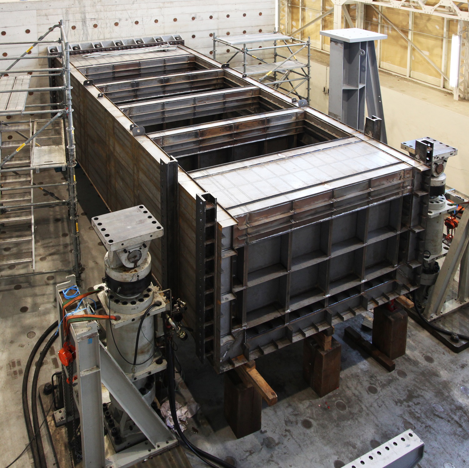
Click the image to enlarge it
Capable of implementing static strength tests and fatigue tests by applying static loads or cyclic loads, which simulate the composite force acting on ships during navigation, by using relatively large structural test models or structural members used as test pieces
Applications:
Implementation of static strength tests and fatigue tests to clarify the damage mechanisms of structural members subject to external wave forces and reflection of test results in the structural design of ships
Recent achievements:
- Clarification of the buckling and collapse behavior of stiffened panels subjected to tensile and compressive load
- Evaluation of the influence of bi-axial and superimposed stress conditions on fatigue crack propagation and growth
- Clarification of the plate thickness effect on fatigue strength taking into consideration secondary processing treatment; provision of part of the data to the International Institute of Welding (IIW) (contribution to the establishment of draft guidelines for fatigue strength improvement through high-frequency mechanical impact treatment)
Recent research:
- Research on the estimation of fatigue crack growth history under bi-axial and superimposed stress conditions
- Research on the plate thickness effect on fatigue strength taking into consideration secondary processing treatment
- Research on the development of a method for evaluating the ultimate strength of stiffened panels and hull girders subject to multiaxial and cyclic load
Analysis System for Materials and Chemicals
〈Analytical system for Materials〉
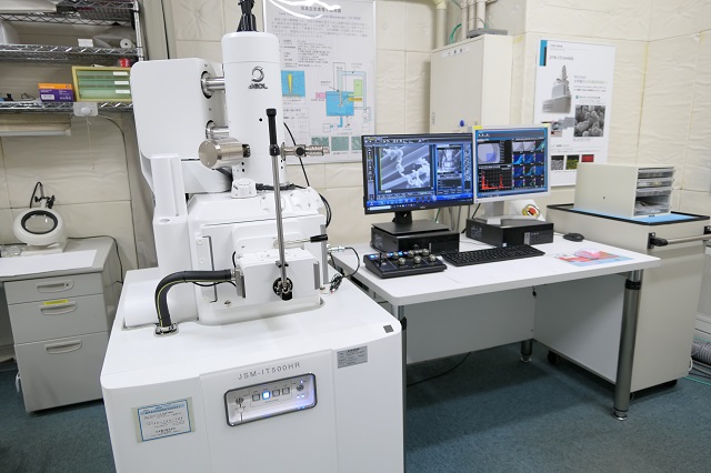
Low Vacuum Field Emission Scanning Electron Microscope (LV-FE/SEM)
High spatial resolution: 1.5 nm (30 kV)
Magnification: x5-x600,000
Accelerating voltage: 0.5-30.0 kV
Low vacuum mode: 10-150 Pa
Large specimen chamber: 200 mmf
Equipped with an EDS analyzer and a CCD camera
Wavelength-dispersive (WD) X-ray fluorescence Spectrometer
X-ray Diffractometer
Click the image to enlarge it
〈Chemical analysis system〉
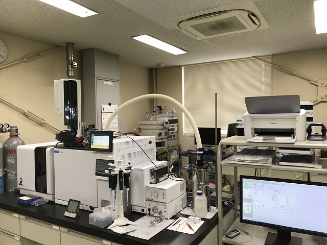
Gas chromatograph mass spectrometer
Ion source: electron impact (EI)
Mass analysis: quadrupole
Mass range: 1-1022 m/z
Liquid chromatograph
Three-dimensional fluorescence spectrometer
Click the image to enlarge it
〈Analytical system for materials〉
Facilities equipped with analytical instruments for microstructural observation and structural analysis of various materials, such as electron microscopes and X-ray analysis
〈Chemical analysis system〉
Facilities equipped with analytical instruments for chemical substances contained in gases and liquids
Applications:
Analysis and measurement methods to evaluate environmentally hazardous substances emitted from ships have been established, which are used for environmental assessments to reduce the environmental impact. Some of our research results have contributed to discussions and proposals at IMO and ISO.
Recent achievements:
Elucidation of the correlation between black carbon and particulate matter (PM) emissions in exhaust gas and engine operating conditions and fuel type
Recent research:
Research on measuring and analyzing methods for emissions when using next-generation fuels
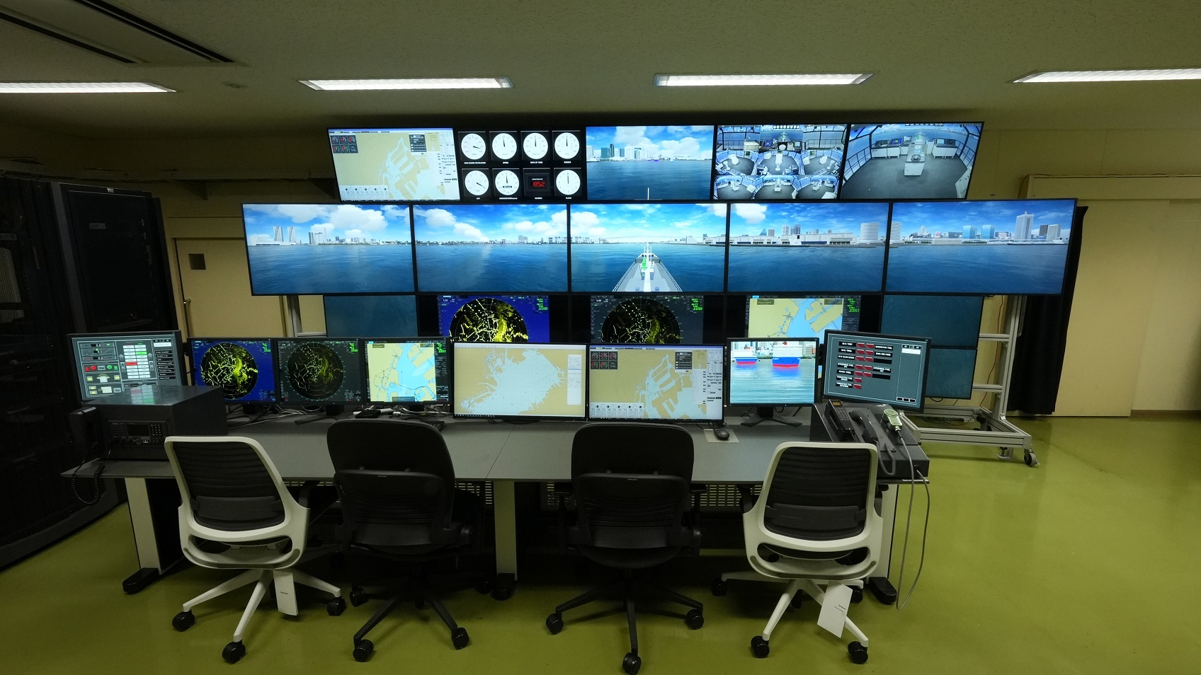
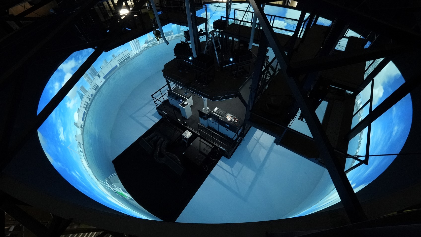
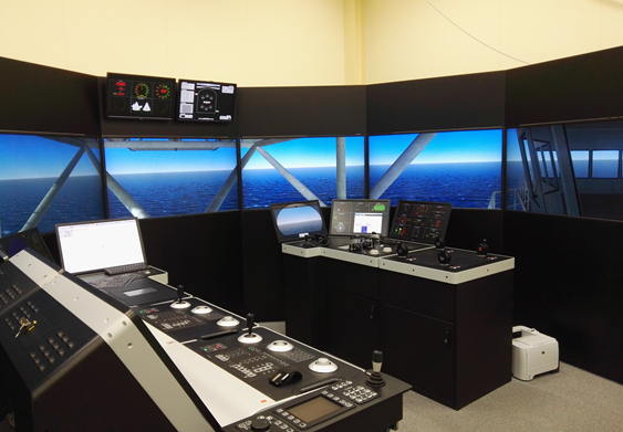
Comprehensive Simulation System
Completed: 2023
Visual System:
Navigational equipment: Repeater compass, Steering stand, S-Band Radar, X-Band Radar, ECDIS, Marine VHF radio, Bridge wing control console,
Virtual binoculars, Overhead panel, Chart table
Others: Bridge monitoring system, Eye-tracking glasses, functional Near-Infrared Spectroscopy (fNIRS) device

Click the image to enlarge it
Capable of reproducing realistic navigation environments for use in analyses of maritime accidents and risks; evaluation and development of navigation assistance devices; research on ship operators’ human factors; and preliminary evaluation of ship tests, including those having new hull forms in actual seas, among others.
Applications:
Contribution to scenario setting for accidents; recording of detailed test results related to navigation, including physiological indexes of ship operators; enhancement of the safety and sophistication of navigation, including that for ship operators
Recent achievements:
- Measurement of the time required to take over a navigational watch from the automatic system.
- Development of a cooperative navigation assist system using inter-ship communication(planned)
- Research on visibility of a pusher barge during short-distance remote control(planed)
Recent research:
- Research on improving the expressiveness of navigation simulators (selection of ocean wave spectrum and simulation of multidirectional irregular waves and concentrated waves)
- Research on navigation and maneuvering assistance technologies using digital image information
Large internal combustion engine facilities
〈Medium-speed marine diesel engine 1〉
Number of cylinders: 3
Cylinder bore: 230 mm
Rated power and speed: 257 kW, 420 min-1
Fuel: Distillate marine fuel/Residual marine fuel
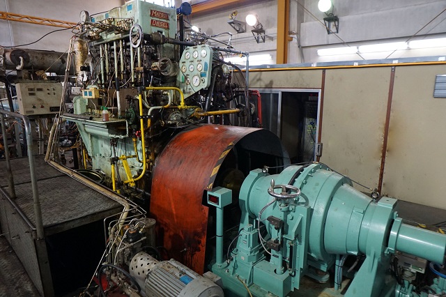
Click the image to enlarge it
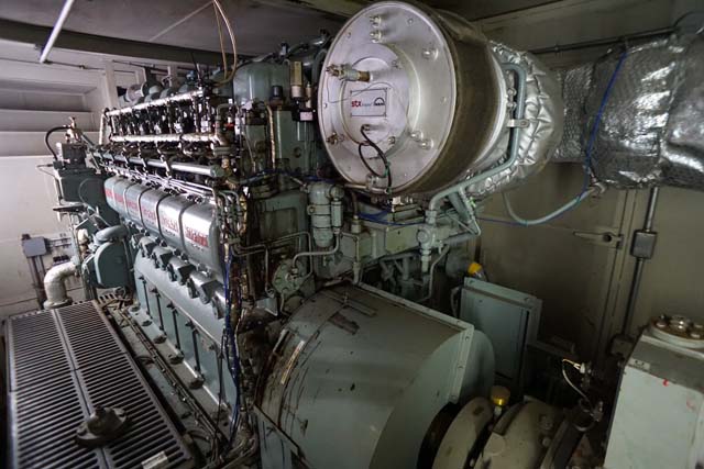
〈Medium-speed marine diesel engine 2〉
Specifications::
Number of cylinders: 6
Cylinder bore: 190 mm
Rated power and speed: 750 kW, 1,000 min-1
Fuel: Distillate marine fuel/Residual marine fuel
Click the image to enlarge it
〈Lean burn gas engine〉
Number of cylinders: 6
Cylinder bore: 155 mm
Rated power and speed: 400 kW, 1,800 min-1
Fuel: City gas
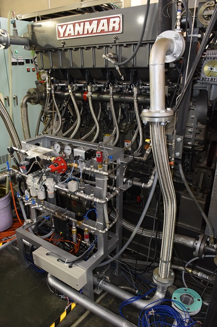
Click the image to enlarge it
- Measuring in-cylinder combustion pressure, engine speed, torque, and temperatures of each part of engines, as well as exhaust gas analysis using various exhaust gas emission analyzers are available. Our medium-speed marine diesel engines facilities are capable of operating on residual fuel oils. Combustion characteristics and safety of any fuel can be evaluated. Additionally, our lean burn gas engine facility allows for research using hydrogen as well as city gas.
Applications:
- Contributions to strengthening the international competitiveness of related industries in Japan
- Contributions to the establishment and development of international standards and guidelines
Recent achievements:
〈Diesel engines〉
〈Medium-speed marine diesel engines〉
- Evaluation of exhaust gas clean process using an exhaust gas after treatment system including SCR and scrubber
〈Lean burn gas engine〉
- Development of technology for hydrogen single-fueled marine lean-burn gas engine
Recent research:
〈Diesel engines〉
〈Medium-speed marine diesel engines〉
- Research that contributes to the safe use of low-sulfur fuel and biofuels
〈Lean burn gas engine〉
- Research on utilization of alternative fuels such as hydrogen and biogas
DP Simulator
 Overview and use of the DP simulator
Click the image to enlarge it