Environment Assessment Research Group
ENVIRONMENT ASSESSMENT
This group conducts research and development of fundamental technologies and environmental impact assessment methods to reduce the environmental impact of ship operations. By reducing the environmental impact of ships, socially rational environmental regulations, and strategic involvement in the formation of international rules, this group contributes to the global competitiveness of the maritime industry.
Members
(◎: Head of the Group)
Research Subjects
For developing technologies that will contribute to a significant reduction in the environmental burden caused by ships, it is crucial to establish appropriate regulations that are socially rational on the basis of an accurate assessment of the environmental burden and to take the lead in formulating international rules from the viewpoint of strengthening the global competitiveness of Japan's maritime industry.
This group has conducted the following R&D activities from this perspective.
- Development of environmental impact assessment methods for air pollution by ship exhaust gas
- Research to prevent marine pollution caused by discharges and spills of oil and hazardous liquid substances from ships
- Research for prevention of transboundary aquatic organism migration using antifouling paints on ship bottoms
- Research on PM emission characteristics from marine diesel engines using portable PM collection device
- Measurement and flammability evaluation of blow-by gas emitted from marine gas engines
- Effect of ammonia mixture in intake air on exhaust emissions from a diesel engine
1. Development of environmental impact assessment methods for air pollution by ship exhaust gas
In response to the gradual tightening of restrictions on air pollutants of anthropogenic origin, this group has been improving our methods for developing emissions data for air pollutants of marine origin, which serve both to identify principal sources of emissions and to identify priority emission reduction categories. Sulfur oxides (SOx), nitrogen oxides (NOx), and particulate matter (PM) contained in exhaust gas from ship engines are air pollutants that not only degrade the air quality but also affect human health. This group evaluates the distribution of emissions of the above air pollutants from ships, distribution changes due to advection-diffusion, and the extent of ship impact on overall air pollution on a global scale (e.g., Figure 1) by developing an analysis system of air pollutant emission using data transmitted from Automatic Identification System (AIS) and performing air quality simulation calculations. The results of these studies will contribute to the proposal of air regulatory indicators that are feasible and scientifically rational.
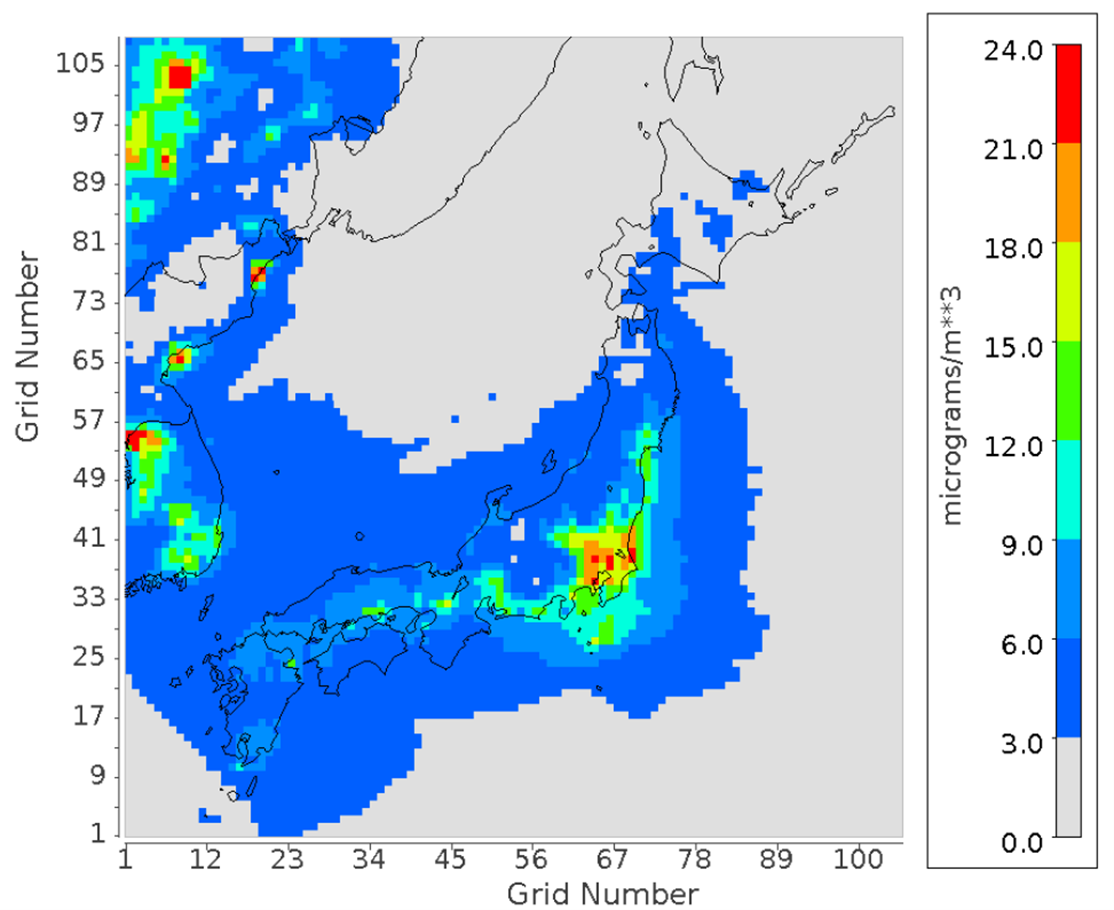
Figure 1 Contribution of concentration distribution of PM2.5 originating from ships
(Reference)
Yokoi, T. et al., Proceedings of Advanced Maritime Engineering Conference 2016 of Pan Asian Association of Maritime Engineering Societies (PAAMES) 221-228, (2016).
2. Research to prevent marine pollution caused by discharges and spills of oil and hazardous liquid substances from ships
When liquid cargo or fuel oil spills due to a marine accident, such as a collision or grounding of a vessel, it is crucial to understand the distribution change of spilled liquid or oil from time to time or the time and amount of liquid or oil drifting to the shore, as well as measures to minimize marine pollution damage. This group has conducted fundamental research on applying oil treatment agents to disperse and treat spilled oil efficiently and the development of oil fences with high oil recovery performance even under severe marine conditions such as rough weather.
Recently, we have been working on developing an efficient method to recover oil that has lost its fluidity due to exposure to low temperatures to prevent oil in the fuel tanks of stranded vessels from spilling into the ocean (Figure 2).
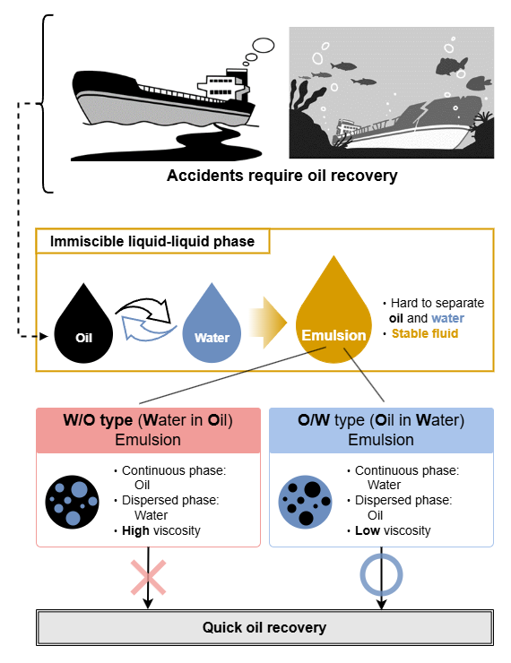
Figure 2 Development of technology for flow enhancement and recovery by emulsifying heavy oil
(Reference)
Ma, X. et al., Experimental Study on Pressure Drop Reduction in Pipe Line Flow of Heavy Fuel Oil by Adding Surfactant Aqueous Solution, The 11th Int. Conf. Multi. Flow, #246, (2023).
The group has improved its diffusion simulation system and applied the technique to assess the impact of external factors on vessels as well as the impact caused by vessels. Figure 3 shows the results of a model simulation of the movement of debris discharged into the marine environment following the eruption of Fukutoku Okanoba, a submarine volcano, in August 2021, to the end of December of the same year. Debris can block the seawater intake for cooling the internal combustion engine of a vessel underway, making the vessel unnavigable. Predictions from model simulations can be used for accident countermeasures or preventive measures.
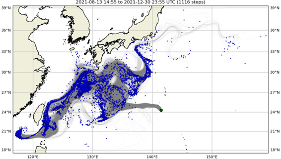
Figure 3 Migration trajectory of debris discharged into the marine environment by submarine volcanoes.
(Reference)
Asami, M. et al., Drift prediction of pyroclasts released through the volcanic activity of Fukutoku-Okanoba into the marine environment., Mar. Pollut. Bull. 186, 114402, (2023).
3. Research for prevention of biofouling accumulation on ships using antifouling technologies
The International Maritime Organization (IMO) has just discussed the guidelines for control and management of biofouling on ships due to concerns that the translocation of invasive aquatic species through biofouling of ships may cause adversely effect to the marine ecosystem. Currently, the antifouling coating systems are the primary means of biofouling among the current antifouling technologies. This group has developed an internationally standardized method for evaluating the efficacy of antifouling paints, which has been already published as the ISO 21716 series. Furthermore, as a bioassay method for the antifouling efficacy, this group investigated a simple detection method for evaluating the pigment of brown algae using spectral measurement. As a result, the efficacy of antifouling paints against the algae can be quantified using the CIELAB color coordinates based on the research results (Figure 4).
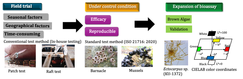
Figure 4(1): Outline of the bioassay method for efficacy of antifouling paints
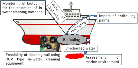
Figure 4(2) Research on underwater cleaning of hulls
(Reference)
Kojima, R. et al., A method for screening antifouling paints using the CIELAB coordinates of Ectocarpus sp. under a flow-through condition, Biofouling, 39, (2023).
4. Research on PM emission characteristics from marine diesel engines using portable PM collection device
Measuring PM emitted from marine engines requires large and complicated equipment that is difficult to transport. For this reason, there are fewer cases of measurement of PM emitted from marine engines. Therefore, a portable particulate matter collection device has been developed to understand the PM emission characteristics of marine engines.
Comparison of the performance of the portable device with existing device complying with JIS B 8008-1:2000 confirmed that the performance of both devices is equivalent.
Taking advantage of the portability of the device, we have conducted PM measurements at heights and outdoors in collaboration with external organizations. Based on these measurement results, methods to reduce PM emissions are being considered.
(Reference)
Ohashi, A. et al., Effect of Sampling Positions along Exhaust Pipe on PM Measurement, Marine Engineering, 54-4, 644-649, (2019).
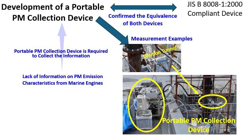
Figure.5 Installation of portable PM collection device at exhaust scrubber outlet
5. Measurement of blow-by gas emitted from marine gas engines and evaluation of their flammability
Blow-by gas is a gas discharged from the crankcase of an engine and is a mixture of exhaust gas, premixed fuel, evaporated lubricating oil, air, and gas produced by combustion. The main components of the blow-by gas are exhaust gas entering through the gap between the piston and the cylinder liner, gases produced by combustion, and premixed fuel.
In automobiles, the blow-by gas is reduced by recirculation, whereas in marine engines, the blow-by gas has never received attention. With the increasing use of hydrogen and ammonia as fuels to reduce GHG emissions, we have investigated the danger of flammable hydrogen or toxic ammonia being present in the crankcase as blow-by gas.
Analysis of the blow-by gas from a gas engine running on city gas as fuel, mixed with hydrogen, showed that the hydrogen content in the blow-by gas reached approximately 4.0% at a hydrogen calorific value mixing ratio of 50%.
This concentration is Lower Explosion Limit (LEL) of hydrogen (the lowest concentration at which flammable gas mixed with air will burn by ignition).
Therefore, it was thought necessary to method ways to reduce hydrogen concentration.
We employ the device that supplies air to the crankcase in our hydrogen engine experiments. The hydrogen concentration in the crankcase is maintained sufficiently low compared to LEL.
As with hydrogen combustion, analysis of the components and concentrations of blow-by gas when ammonia is co-combusted is underway.
(Reference)
Nakamura, M. et al., Compositional analysis of blowby gas from lean-burn gas engine and evaluation of gas combustibility in crankcase during hydrogen co-combustion, Papers of National Maritime Research Institute, 22-3, 327-340, (2022).
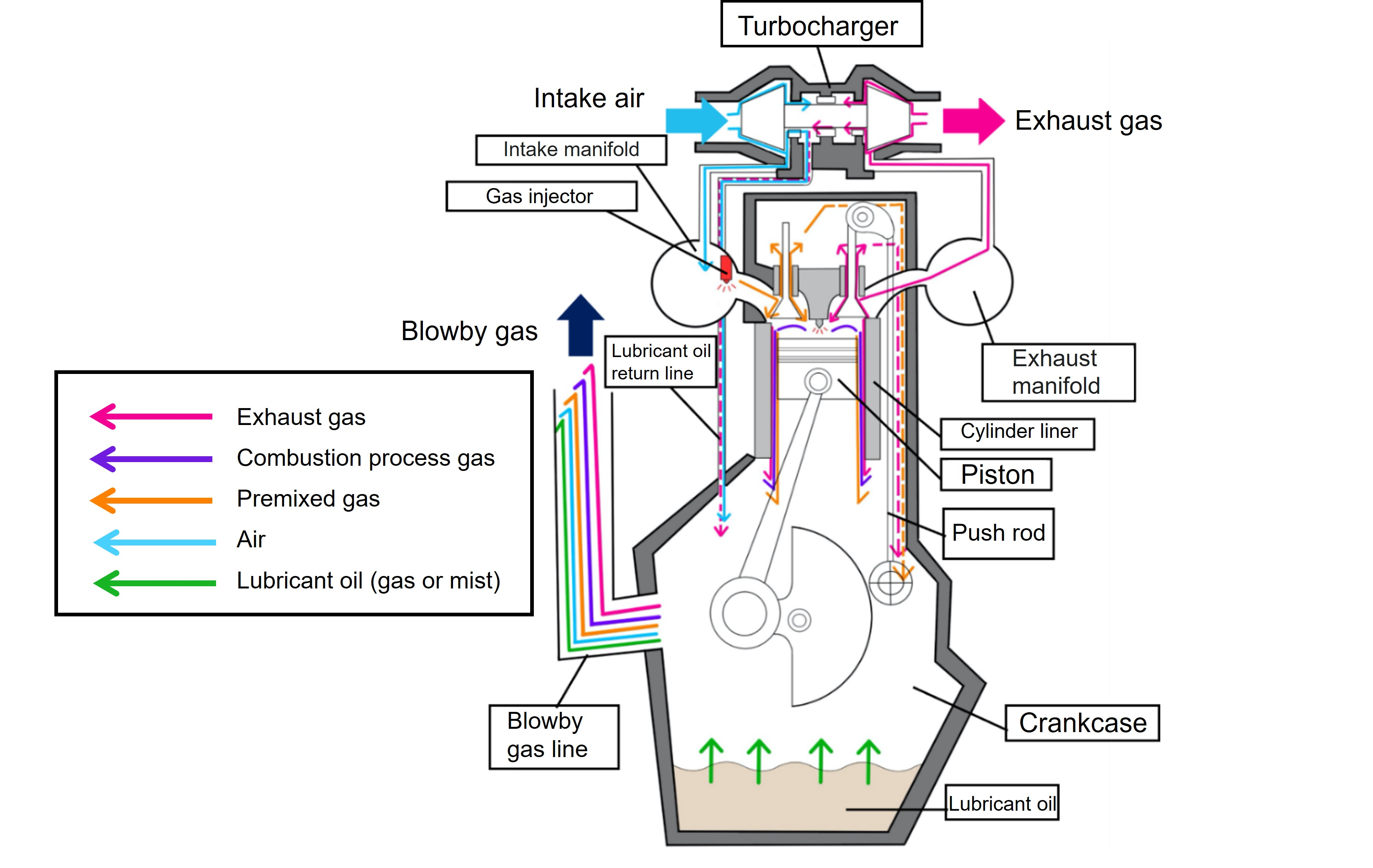
Figure.6 Conceptual diagram of blow-by gas
6. Effect of ammonia mixture in intake air on exhaust emissions from a diesel engine
As part of the global warming countermeasures, we have been conducting research into mixing ammonia into the intake air of diesel engines, and have shown that this reduces greenhouse gases in the exhaust.
Here we introduce changes in the emission characteristics of particulate matter (PM), which is believed to have an impact on human health.
It was found that when 70% ammonia was added in terms of calorific value (70% NH3), PM concentration was reduced to about one-third of that when diesel oil alone was burned.
In addition, analysis of the PM components revealed that the decrease in PM concentration with an increase in the ammonia mixing ratio was due to a decrease in elemental carbon, and that the main component of PM at 70% NH3 was organic carbon.
(Reference)
Ohashi, A. et al., Effect of Ammonia Mixture in Intake Air on PM Emissions from a Diesel Engine, 94th Annual Meeting of JIME, OS3-8, 175-176, 2024
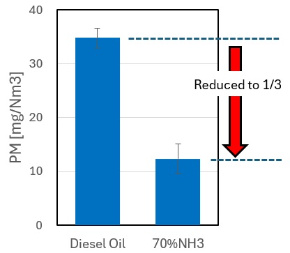
Figure.7 Effect of Ammonia Mixture in Intake Air on PM Emissions from a Diesel Engine