Environmentally-friendly Engine Research Group
ENVIRONMENTALLY-FRIENDLY ENGINE
This group analyzes spray and combustion phenomena by simulation and visualization measurements to understand physical phenomena related to engines and to reduce the fuel consumption rate and harmful emissions of engines. We principally use a rapid compression machine (RCM) for the experiment. This device can control the temperature, pressure, and composition (gas-fuel premix or CO2,O2 concentration) of the intake air to meet various atmospheric conditions. It has the character of its ability to perform visual image measurements (shadowgraph, two-color method, radical spectroscopy, etc.) of premixed combustion and diesel spray combustion, exhaust measurements (NOx,O2,CO2, CO, soot, HC (hydrocarbons), etc.), and wall heat flux measurements. In addition, we also use a constant-volume chamber that can handle low temperatures and form swirling flows and a fuel combustion analyzer (FCA) to test fuel ignitability.
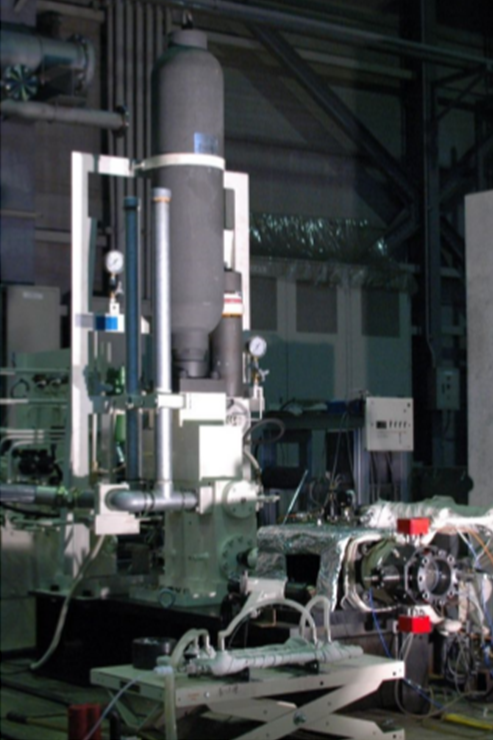
Rapid Compression Machine
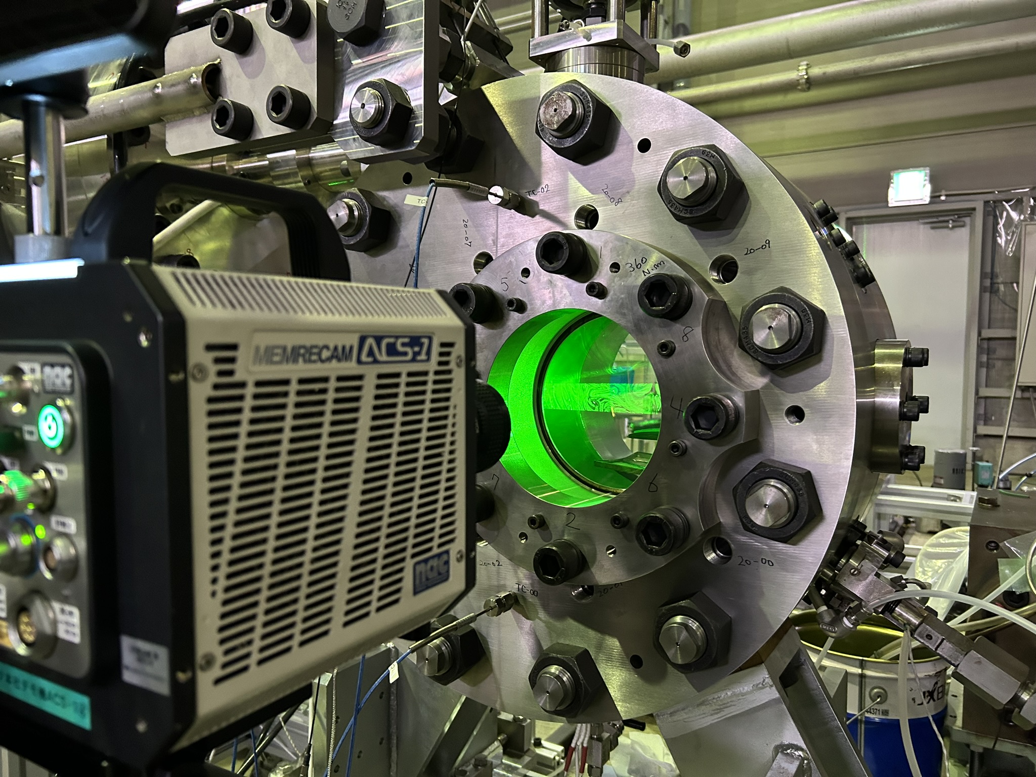
Constant-volume Combustion Chamber
Members
(◎: Head of the Group)
Research Subjects
1. Ignitability/combustion analysis of alternative diesel fuel
In response to recent demands to reduce greenhouse gas emissions, various fuels are being proposed as candidates to replace light and heavy oil. We are conducting research on liquid fuels that have high energy density and can be applied to existing infrastructure, focusing on blending with existing fuels and on gas fuels that are being developed as marine fuels, focusing on direct fuel injection into the cylinder.
In a diesel engine (an engine in which fuel is injected directly into the cylinder), we inject liquid fuel into the high-temperature and high-pressure cylinder. After atomization and evaporation, the chemical energy of the fuel is converted into power through ignition and combustion, which means that the air-fuel mixture and subsequent ignition of the used fuel are critical. However, the ignitability varies depending on the fuel used, and in particular, the alternative fuels currently envisioned have a broader range of ignitability than the conventional-used petroleum-based fuels. Therefore, we will continue to study various fuels to respond to any fuel that comes our way.
| Compound | Formula |
CN [-] |
Hl [MJ/L] |
|
|---|---|---|---|---|
|
Liquid |
Methanol | CH3OH | 2 | 16.8 |
| Ethanol | C2H5OH | 2 | 21.9 | |
| Methyl oleate | C19H36O2 | 56 | 32.7 | |
| Methyl palmitate | C17H34O2 | 74.3 | 29.5 | |
|
OME3 (tetraoxanonane) |
C5H12O4 | 78 | 19.5 | |
|
OME6 (heptaoxapentadecane) |
C8H18O7 | 104 | 19.8 | |
| Diesel fuel | – | >45 | 36.7 | |
|
Gas |
Hydrogen (35MPa) | H2 | – | 3.8 |
| Ammonia (35MPa) | NH3 | – | 11.8 | |
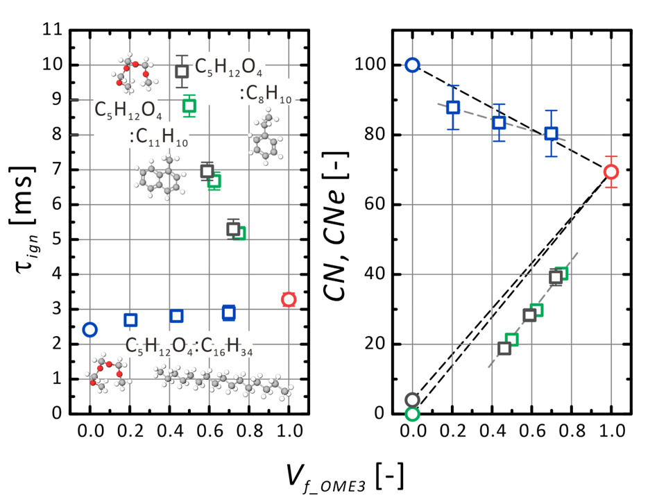
Relationship between volume fraction of OME3, ignition delay, and cetane number
(OME3 mixed with hexadecane, 1-methylnaphthalene, ethylbenzene)
Radicals in fuel spray combustion
(upper; C2 radical, lower; OH radical)
2. Ignitability analysis of micro-liquid fuels in fuel-air premixture
When gaseous fuels such as hydrogen, ammonia and natural gas are premixed with air and supplied to the engine, a trace amount of liquid fuel is injected into the premixed gas to serve as an ignition source, which is called the micro-pilot method. Compared to ignition with spark plug used in gasoline engines, this method is more complex with the added elements of atomization and evaporation of liquid fuel and a binary fuel mixture of liquid and gaseous fuels. For this reason, the mechanism is yet unclear. Unlike diesel spray combustion, in which fuel is ignited and burned during the fuel injection period, microinjected fuel moves through the cylinder while diffusing and mixing between the end of injection and ignition. Therefore, the behavior of micro-fuel atomization is crucial, and we are studying the relationship between fuel ignitability and the ignition process while using injection pressure, two-stage injection, etc.
Variation of ignition and flame spread with pilot fuel injection pressure Pinj
((upper row; Pinj=50MPa, middle row; Pinj=90MPa, lower row; Pinj=130MPa))
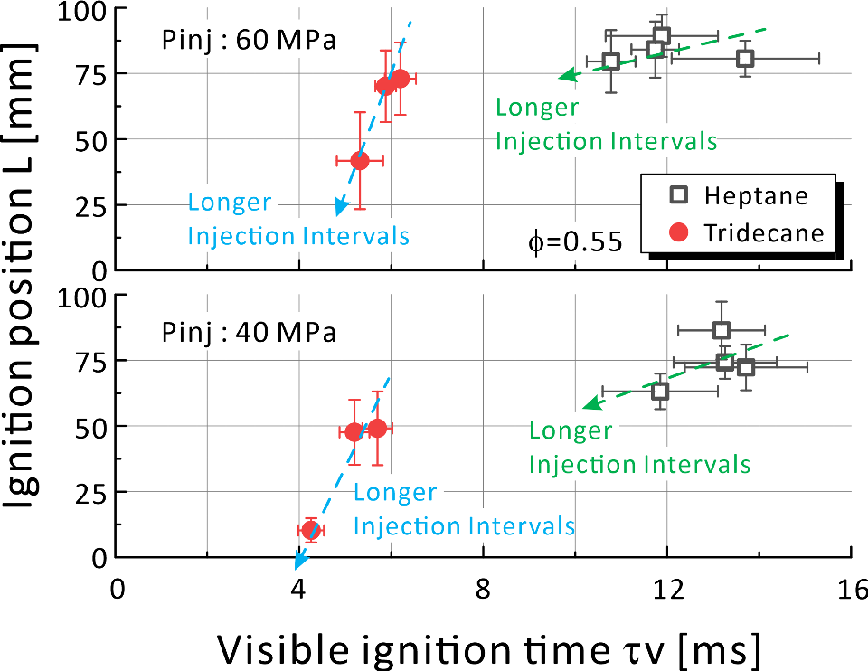
Relation between ignition timing and position when the two-stage injection interval of pilot injection is changed.
3. Modeling of fuel spray
Three-dimensional spray combustion simulations in diesel and gasoline engine cylinders are becoming available for practical design and prediction. Among them, numerical simulation of gas-liquid two-phase flow related to fuel spraying requires various models for each phenomenon (droplet flight, droplet splitting/coalescence, droplet evaporation, etc.), and each model is not valid under all conditions and can be used only under limited conditions. Therefore, comparison and verification with experiments are always necessary, and models with a broader range of applicability are required.
So far, we have been in charge of the development and implementation of the spray part of 3D-CFD software "HINOCA" in the "Innovative Combustion Technology" (2014-2018) project under the Cross-ministerial Strategic Innovation Promotion Program (SIP). Starting in FY2019, we are working on clarifying the causes of the different spray shapes each time fuel injection is performed in experiments, proposing and improving models to reproduce this, and conducting experiments and modeling of the re-flying of wall-attached fuel and spray behavior in low-temperature fields. In FY2023 and 2024, the spray model was verified for various fuels. From FY2025, predictions of evaporation of wall deposition fuel will be carried out for fuels mixed with alternative fuels.
We did a part of this research in collaboration with universities and research institutions through joint research with engine manufacturers. (Click here for a book with more information on the spraying model.)
On the other hand, various methods have been proposed and studied for predicting the amount of air introduced into the entire spray and the air-mixture formation process, including the momentum theory of Wakuri. We have extended the 1D spray model of Musculus and Kattke to include the temperature in the spray from fuel evaporation to ignition. We are investigating the variation of the equivalent ratio and average temperature in the spray axis during alternative fuel injection.
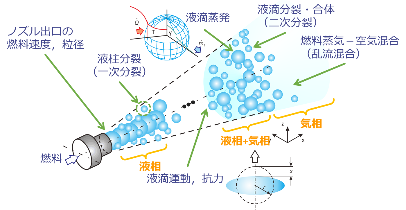
Physical model and image of spraying
Non-evaporative fuel atomization simulation
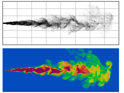
Evaporative spray simulation (top: droplet, bottom: evaporated vapor)
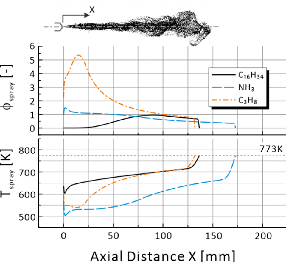
Temperature and equivalent ratio distribution in the spray of alternative fuel evaporation atomizer
(Ta=773K, Pa=5MPa, Pinj=80MPa)